
L. Fenyvesi, A. Csatár, M. Szente
National Agricultural Research and Innovation Center (NAIK), Institute of Agricultural Engineering, Gödöllő, Hungary –
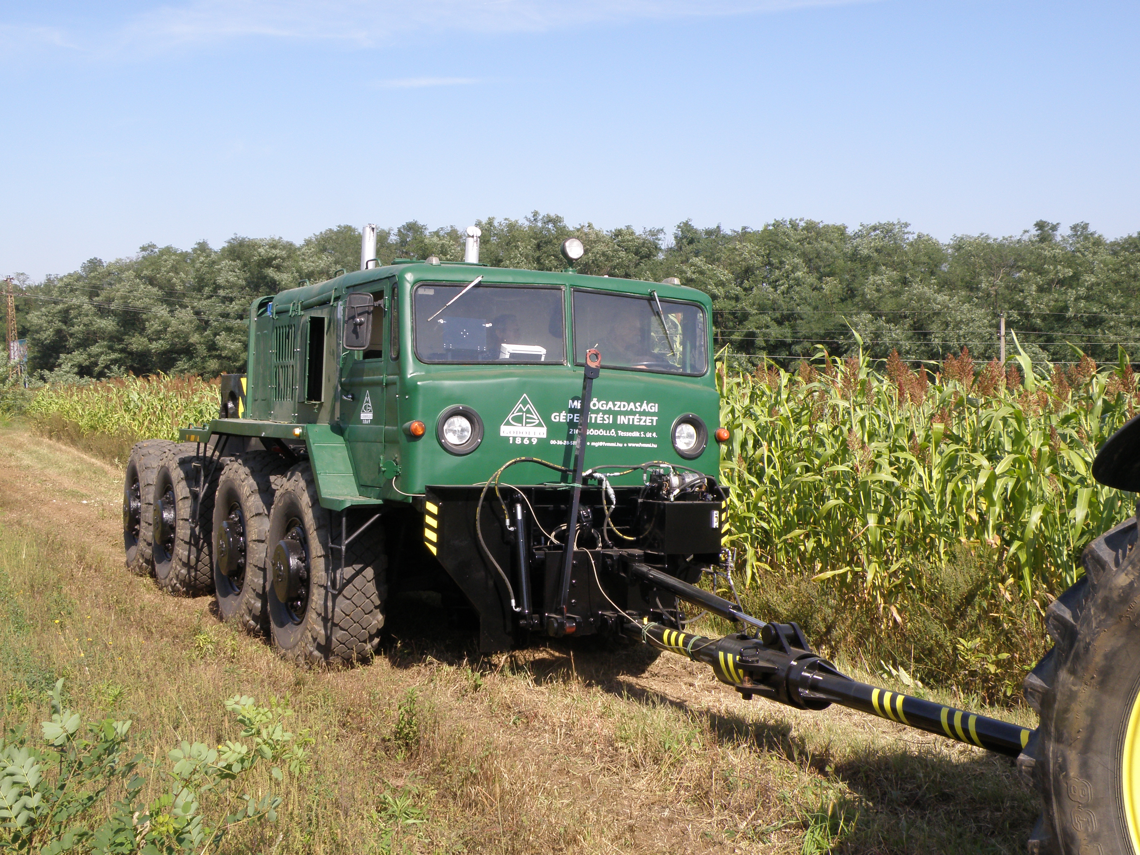
A new dynamometer vehicle was developed by the Hungarian Institute of Agricultural Engineering (MGI) to determine the traction performances of agricultural tractors on soft soil (fields) and on hard surfaces. The braking system of the vehicle is a special diesel-hydraulic version with 400 kW of power. Drawbar-force and travel-speed measurement and control and real-time data analysis are realised with a Programmable Logic Controller (PLC) control unit and Personal Computer (PC) data collection. The dynamometer vehicle developed is not only suited to the determination of the performance data of agricultural tractors on fields, it is also useful for research and development testing of tractors.
Dynamometer vehicles used in test institutes for testing off-road vehicles and agricultural tractors are usually made for use on asphalt or concrete roads and cannot be used on fields or terrain. On other case, the existing dynamometer vehicles useful for field test have a significant limit of drawbar force and drawbar power (Filho et al., 2008; Kathirvel, Balasubramanian, and Manian, 2000; Leviticus, 1980). The current method of measuring the performance of agricultural tractors approved by different International Standards is to measure the drawbar power over a range of gears on a test track using an instrumented load car. This is why these vehicles are useful only on test tracks. It is well known that the traction characteristics of a tractor depend on the following: 1) the tractor construction and driveline (Bashford, Woerman and Shropshire, 1985; Zoz and Wiley 1995), 2) the mechanical properties of the soil (Söhne, 1961), and 3) the interaction of the tyres (or track system) with the soil (Komándi, 1990; Sitkei, 1972; Söhne, 1961). This means that for tests of agricultural tractors and other off-road vehicles to have value, they must be made on soft soil (fields). Therefore, the analysis of drawbar force and power is important from not only a practical but also a theoretical perspective.
The need to have the value of off-road vehicles led the NARIC Institute of Agricultural Engineering (MGI) to develop a new dynamometer vehicle. The goal of development was to create a dynamometer vehicle that can be used on fields to determine the traction characteristics of agricultural tractors and other off-road vehicles. Moreover, the vehicle must be suitable for R&D activities, such as testing different track systems of off-road vehicles, soil-wheel interactions and mobility of other types of vehicle (e.g., military vehicles).
Description of the dynamometer vehicle
The basic vehicle
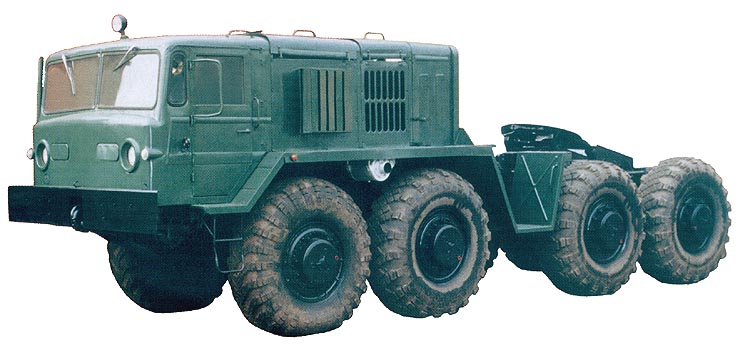
To construct the dynamometer vehicle, a MAZ-537 military pulling vehicle was used (Fig.2). This vehicle has eight driven and independently suspended wheels, and its traction capability is excellent.
To make it suitable for use as a dynamometer vehicle, the following modifications were made to the construction:
the original Russian engine was changed to a 400-kW IVECO V8 Cursor engine,
the original transmission system was changed to a hydrostatic drive, and the functions of the original power-transmission elements were taken over by the built-in hydrostatic-drive-system equipment (pumps, hydraulic motors, valves, and pipes), which enable controlled driving,
a drawbar system was fitted to the front of the dynamometer vehicle to make a suitable connection between the dynamometer vehicle and the test vehicle (it has an adjustable connection height for horizontal positioning and allows a pushing force to be applied to the test vehicle for the measurement of motion (rolling) resistance),
a PLC was built in for control and for monitoring and display of the main parameters.
Requirements of the dynamometer vehicle
Two modes of operation are necessary: normal drive mode, for moving from site to site, and braking mode. The speed range of both drive modes is 0–35 km/h.
The dynamometer vehicle must move with stepless active drive (continuously variable transmission).
The pulling force must be infinitely variable between 0 and 150 kN.
The drawbar power must be infinitely variable between 0 and 250 kW.
The controller of the braking force and the travel speed of the dynamometer vehicle must be able to run a predetermined speed or braking-force plan.
In case of an emergency, the driver must be able to take control of the vehicle immediately.
Two modes of control are necessary: force-control mode, for when the towing force varies greatly, and speed-control mode, for when the towing force varies little but the speed varies greatly.
Application of the device
The dynamometer vehicle as a self-propelled vehicle has a closed hydrostatic drive with a closed control system.
The pump unit is fitted directly onto the flywheel of the diesel engine via a clutch; thus, its rate of revolution is equal to the engine speed. The pump unit has two pumps with the same axle but independent suctions and pressure lines. The first pump is an axial-piston variable pump with a swash plate and the second is a boost pump that acts as a feed.
The wheels of the vehicle are driven via two axial-piston variable hydro motors fitted onto the gearbox built into the driveline. Another original gearbox in the driveline ensures two speed steps.
The auxiliary pump prevents overspeeding of the diesel engine when its torque is not high enough to eliminate the set brake torque.
Software and operation of the dynamometer vehicle
General function
A dynamometer vehicle application was developed to control the hydrostatic drive system to keep a constant speed and braking (pulling) force, which can be set by the operator with a toggle switch while the vehicle is being pulled. Additional braking force is applied by a separate hydraulic braking circuit with a hydraulic motor and a proportional pressure valve, which is also proportionally controlled. The actual and set values of the braking force and speed are shown on the Di2 display (An LCD, graphic (240×128), monochrome, adjustable contrast/brightness display for displaying process variables, data input and diagnosis).
For non-braking operation, there is a normal drive mode in which speed is controlled by the accelerator pedal.
The application also monitors the pressure in the hydrostatic drive circuit, diesel overspeed and diesel overload during braking mode and normal drive mode and adjusts the speed (conditions) to keep the machine parameters at a safe level.
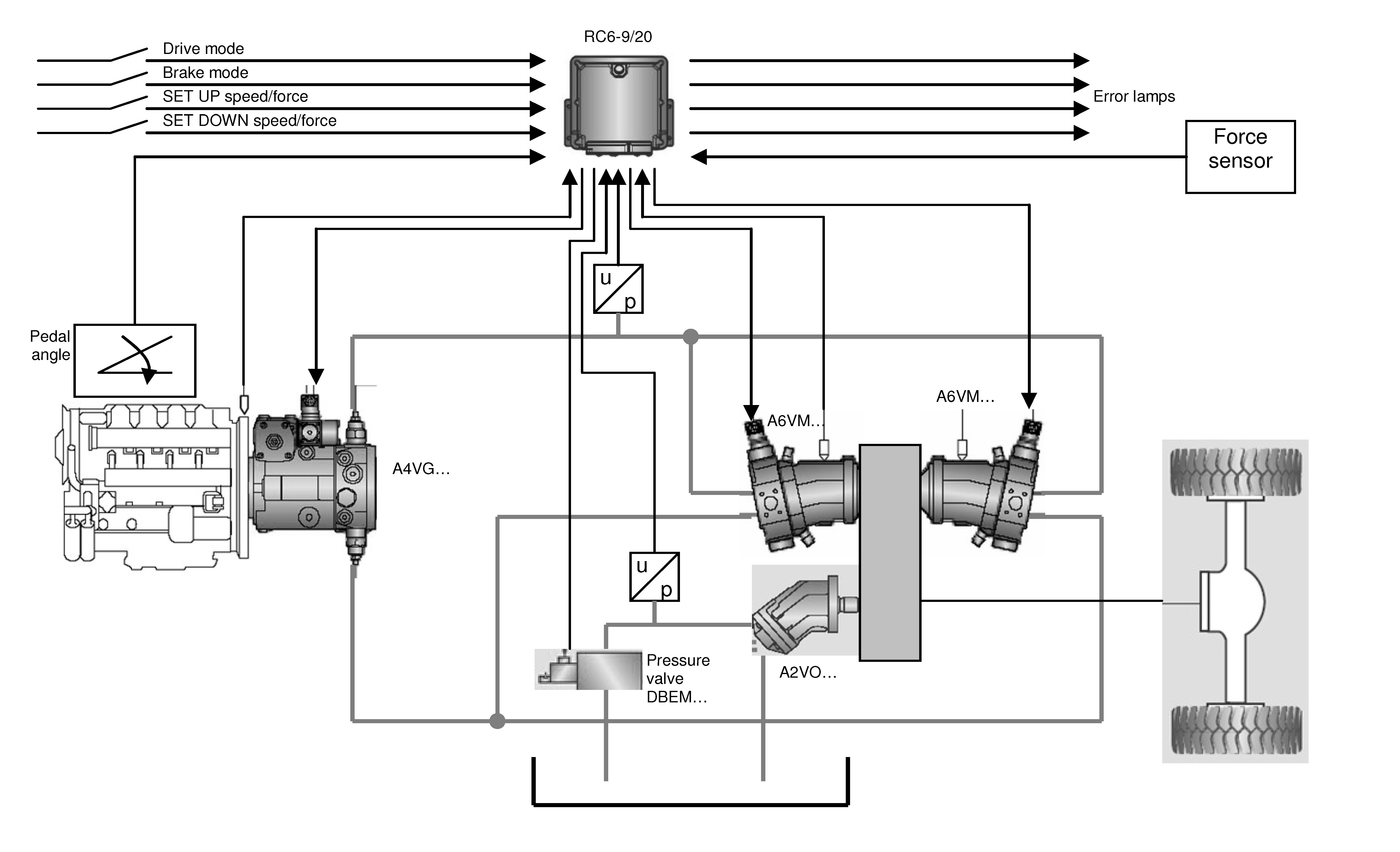
Main application components (Fig. 3):
Actuators:
pump proportional-control drive circuit;
motor proportional-control drive circuit;
constant motor for hydraulic additional braking circuit.
Sensors and control:
RC6-9/20 controller unit – used for the programmable control of proportional solenoids and additional switching function. It can therefore be used for hydrostatic travel drives in vehicle. The controller consist of a powerful 16 bits microcontroller, 6 proportional and 9 switched outputs, 8 analog inputs and 5 frequency input, RS 232 and CAN BUS. The RC6-9/20 controller is manufactured by Bosch Rexroth AG;
display;
pedal-angle sensor;
pressure sensors;
temperature sensor;
hydro-motor-speed sensor and diesel sensor;
external-force sensor (Tensile/compressive force transducer, type: U2B. Nominal force: 200 kN. Class of Accuracy: 0,1. Rated sensitivity: 2mV/V. Manufactured by Hottinger Baldwin Messtechnik GmbH);
BODEM (Control software of the dynamometer vehicle).
Description of the operation
The RC6-9/20 with the dynamometer-vehicle software controls the two EP hydraulic motors (Electric Control, With Proportional Solenoid) using the DA hydraulic pump (Hydraulic Control, Speed Related) and DBEM pressure valve (Proportional Pressure Relief Valve).
There are two drive modes: normal drive mode and braking mode, with vehicle speed controlled by setting the speed or braking force of the closed-loop controller. Selection between modes is made with the drive-mode switch.
The automotive drive system is realised by a pump and two parallel EP motors controlled via the pedal-angle signal.
Monitoring functions are built in to keep the machine operating in safe conditions (diesel-load-limit control, diesel-overspeed control, overpressure control, and fault detection). These functions influence the vehicle speed and braking-circuit pressure valve to achieve the set work parameters.
Normal drive:
During normal drive, the driver has full control over the vehicle, and the speed depends on the accelerator-pedal angle.
The desired speed in normal drive mode is reduced by load-limit control. The load limit is evaluated by the diesel engine speed drop in comparison with the known curve of speed vs. pedal angle.
Braking mode (pull mode):
In this mode, the vehicle is pulled by another vehicle, and the controller algorithm controls speed or force (depending on operator choice).
The speed of the vehicle is controlled by setting the value of the speed or force (set by 2 switches, set UP and set DOWN). The sensitivity (scaling) of the control is adjustable.
The braking-force signal is supplied by an external sensor (attached to the drawbar) that measures braking force. The sensitivity (scaling) of the control is adjustable.
Machine states:
Start locked: waiting for starting conditions after power up; outputs are not active; indicated by blinking error lamp.
Park mode: no drive direction has been chosen; machine stands still; outputs are set to minimal values.
Drive-forward mode: forward driving is possible; speed depends on the accelerator-pedal signal.
Drive-backward mode: backward driving is possible; speed depends on the accelerator-pedal signal.
Force-braking mode: force controller is active and controls the speed of the vehicle to set force values; only forward driving is possible.
Speed-braking mode: speed controller is active and controls the speed of the vehicle to set speed values; only forward driving is possible.
Fault error detected: information about the fault type is displayed; reaction depends on the drive mode.
Measurement and data-collection system
The measurement and data-collection system has three main parts:
Signal converters
SPIDER8 data collector – a multi-channel PC based data acquisition system manufactured by Hottinger Baldwin Messtechnik GmbH. All of 8 channels in the Spider8 provide excitation for passive transducers, amplifier, filters and its own A/D converter. All A/D
converters operate up to 9600 measurements/s from each channel with a resolution of 16 bit.
Laptop for data storage and display
The main data acquired are:
Drawbar force, from a Hottinger load cell
Travel speed, from a fifth wheel and a radar sensor
Weather station data
Wheel speed of the tractor
Fuel consumption, from a Pierburg PLU
Temperatures of the different mediums.
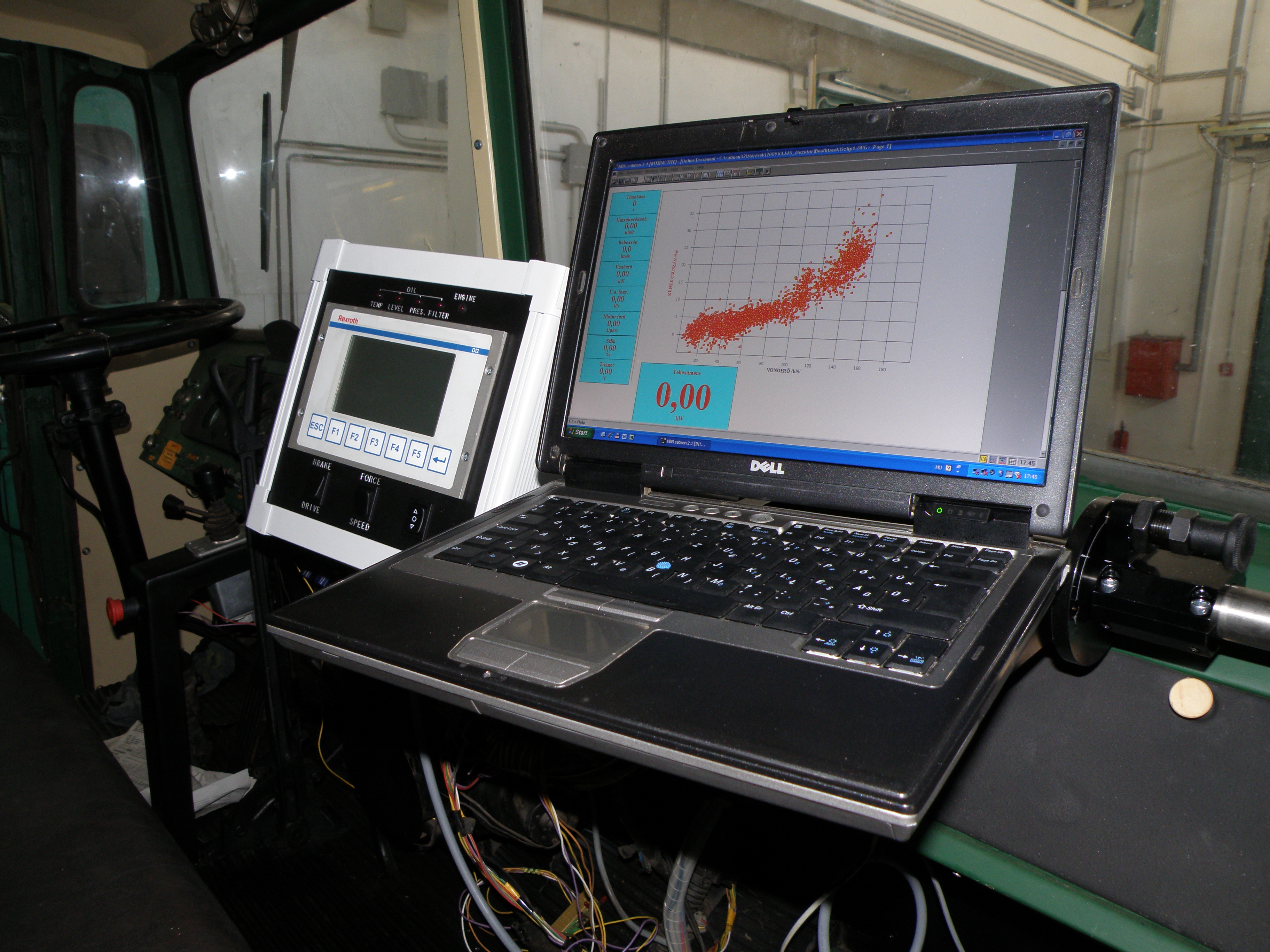
The signal converters and the data collector are located on the test vehicle, ensuring short cabling to the signal transmitters. Two SPIDER8 collectors with 16 channels were used, but this can be extended. The control of measurement and the real-time display of the data (graphically) are accomplished inside the dynamometer vehicle (Figure 4).
The measured data are stored, and detailed evaluation is carried out by postprocessing.
Results, available tests
With the help of the new dynamometer vehicle, there are potentialities to make special tests, in addition to common drawbar tests, that are instrumental in production development (mainly of tractors). These potentialities are the followings:
Drawbar testing on a field.
Continuous testing of tractor behaviour, traction and drawbar performance for a given travel speed (the dynamometer vehicle ensures constant (stable) travel speed (speed control), and the input values for the test tractor are variable).
Continuous testing of tractor behaviour, traction and drawbar performance for a given drawbar force (the dynamometer vehicle ensures constant (stable) drawbar force (force control), and the input values for the test tractor are variable). The drawbar-force demand (that is, the average of it) of a given pulled implement can be simulated with the appropriate choice of drawbar force.
Discussion
We have done experimental field tests with the dynamometer vehicle. During the experimental tests we used two types of tractors. The first one had a “common” powershift transmission; another one was equipped with continuously variable (step less) transmission (CVT).
The experimental tests were done by two methods:
Method 1: increasing or decreasing the drawbar pulls step by step each point on the plot represents the average of 15 seconds of data sampled at 10 Hz. The drawbar performance characteristics were calculated with the help of regression curves of averaged data plots.
Method 2: increasing or decreasing the drawbar pulls continuously by uniform speed each point on the plot represents a data sampled at 10 Hz. The drawbar performance characteristics were calculated with the help of regression curves of sampled data plots.
Every method was useful for powershift tractor test. But during the second method we needed to change the increasing (decreasing) speed of the drawbar pull to reach the scaling when the performance characteristics of the tractor were close to the first method results. Using this method it is possible to reduce the length of the measuring section i.e. the effect of the soil characteristics changes on the test result.
In the case of continuously variable transmission using the first method it was necessary to harmonize the control system of the dynamometer vehicle with the tractor transmission-engine control system i.e. the reaction speed of the dynamometer vehicle control system had to set under the reaction speed of the tractor control system. Otherwise there were happened swinging.
Conclusions
The dynamometer vehicle constructed from a military vehicle (MAZ 537) is a suitable device for testing the agricultural tractors on the field to determine the drawbar performance characteristics.
In case of the tractors equipped with “common” stage transmission the dynamometer vehicle is suit for done the test by static (increasing or decreasing the drawbar pulls step by step) and dynamic method (increasing or decreasing the drawbar pulls continuously) as well.
For testing the tractors with continuously variable transmission it is necessary to harmonize the control system of the dynamometer vehicle with the tractor transmission-engine control system.
For further information: fenyvesi.laszlo@gmgi.hu, www.gmgi.hu


Your article is very excellent, to make me understand better about how to test draw bar pull of the tractor. I hope we can discuss further all of the result of draw bar pull test and how to measure. It is important for me because I work in Center for development Agriculture Machinery in Indonesia.
If it is possible, I need take its training. Also please inform me, how much maney must I pay for this training. Thank you and see you next time.
Dera Sir,
we are glad to know you found this article very excellent.
For further information about this matter, you could directly contact the Author, Prof. F. Laszlo, to the following address: fenyvesi.laszlo@gmgi.hu, http://www.gmgi.hu
Kind regards
Anna Bonanomi
Dear sir/Madam,
your post is very informative and related with our work,as i am an agricultural engineer at CFMTTI,budni ,India.And we are having an instrumented load car ERF and another one very old hydro-mechanical pulling device made by Reynolds boughton engg. england since1960’s, in which the loading is through a hydraulic valve-circuit that restrict the flow of pump i.e.driven through a mechanical transmission(Probably of fordson tractos) from traction wheels of 18.4-32 tyre.And we are trying to rebuild this one ,whether you have any inputs regarding this hydro-mechanic loading device. i am also very much interested to learn in this area .Thanx and regards,
R. Paliwal ,
Agricultural Engineer,
CFMTTI,Budni ,India
Dear Eng. Paliwal,
I thank you for appreciating the content of our magazine Power Transmission World.
For any information request about this new agricultural transmission, you could directly contact the Author, Prof. Fenyvesi Laszlo:
fenyvesi.laszlo@gmgi.hu, http://www.gmgi.hu
Best regards
Anna Bonanomi
editor
wow it is an excellent article that i have read so far regarding draw bar pull measurement,previously draw bar pull is measured with dynamo-meter and know your finding dynamo-meter vehicle will increase the precision and accuracy in measuring the power from tractor to pull an implement.nice work
Good Innovation.
My new email address: fenyvesi.laszlo@uni-mate.hu
Dear Prof. Fenyvesi,
thanks a lot for informing us about your new email addres.
Kind regards,
Anna Bonanomi
Editor