
Pál Bogár, Sincroll Drive Technologies –
A novel mechanism for gearing is presented that uses balls to intermediate between the input and output wheels. The balls carry out pure rolling without sliding while rolling along grooves on the surfaces of the two wheels facing each other. Inside the gear, the ball-wheel contact is the same as in all ball bearings in general while, outside, the system works the same as any gear – hence the slogan ”Bearings for Gearing.” The technology shows a large variety of potential advantages including very high efficiency and no back-lash as well as high contact factor and large flexibility in design. Several prototype tests have proven the concept and a large number of customer design projects show the interest from the markets.
To reduce sliding friction and thus improve the efficiency of gears has been as ever an important topic in the field of gears and transmissions engineering. Considering the wide spread use of gears and drives in the machinery industries, a 50-100 billion euro market depending on how you look at it, the technological and economic impact of potential energy savings as a result of efficiency improvements would be just tremendous – not to mention recent political and societal movements towards energy conservation, green energies and climate change management.
This was the original motivation for us too when we proposed to reduce sliding friction between the driving and driven surfaces in gears via the introduction of a new coupling element: a ball (roller in general). We asked the question, can we maintain pure rolling of the ball between the driving and driven surfaces throughout the entire process of coupling in the mechanism and thus get rid of sliding friction all together – will the theoretical physical model provide a solution for the kinematics? Because if yes then energy losses could be reduced by a factor of anywhere between 10 to 100 considering the difference between energy dissipation in sliding friction and rolling resistance. The answer we found was yes, there is such a solution to the physical problem.
A new paradigm for gears
We also found out that the new mechanism not only makes it possible to reduce energy losses but in fact results in a new, fundamentally different and complete framework – a new paradigm for mechanical gearing. It creates a new alternative gear universe that competes with the old gear universe across the entire board – not only regarding energy efficiency but along a whole list of other technical and commercial factors.
Kinematics
One can think of the coupling elements: the balls in our mechanism as kind of teeth that have been detached from the wheels that carried them while fixed together in conventional involute gears. The balls’ centre of mass (CM) movement is independent of that of the wheels now and is determined by the constraints for pure rolling motion only, nothing else. This has far reaching consequences.
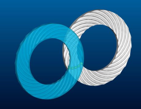
Overlapping wheels with balls between them
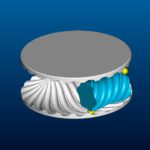
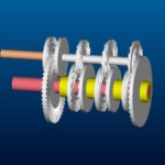
First of all, since the balls are not fixed to the perimeters of the wheels – and not forced to work at the presence of sliding friction as it happens to the teeth in involute gears – they are allowed to move away from the perimeters as pure rolling requires them to thus creating the trade-mark appearance of the system: overlapping wheels that are linked together by balls between them rolling down along grooves on the frontal surfaces of the wheels facing each other, see Figure 1 as an example below.
The balls travel along a special trajectory in the laboratory space as they couple the two wheels together under the transmission function, as shown in Figure 1 above, and the trajectory is projected onto the rotating wheels’ surfaces determining the pattern of the grooves. In fact, the pattern of the grooves on the surfaces of the wheels is the key to drive the balls along the proper trajectory and realise the required translation of the input into the output movement – all information such as the gearing ratio is contained within the spatial lines and the overall pattern of the grooves. Considering the balls’ trajectory used in the mechanism, we also call it the coupling path, the balls enter one end and exit at the other end of the coupling path – between the two ends they are re-circulated in a separate device such as a simple pipe.
 Extra degree of freedom: free parameter to choose: large variety of solutions
In fact, by moving the coupling elements that used to be the teeth before but are now the balls away from the perimeters of the wheels and towards the wheels’ frontal surfaces we are introducing an extra degree of freedom to the system and thus it becomes one dimension richer than conventional involute gears. This means that the balls are not fixed to the perimeters now but can move along the points of the overlapping surfaces of the wheels governed by the pure rolling constraints. In other words, the differential equations that describe the system under pure rolling conditions produce infinitely many solutions for the ball trajectories corresponding to the infinitely many initial conditions that we can specify. While the location of the ball trajectory is determined by the gearing ratio uniquely its size is arbitrary and can be selected freely i.e. based on other considerations such as application requirements.
From a practical point of view, this means that for each gearing problem specified by the centre distance and the gearing ratio we have a large number of (theoretically infinitely many) solutions corresponding to arbitrarily variable initial conditions for the ball trajectory. All these solutions correspond to legitimate gear realisations that, while performing exactly the same way in terms of their kinematics such as input/output movements and gearing, can show totally different constructs in terms of their wheel and ball sizes, ball numbers, overall shape and size and operational features like speed, noise and load capacity.
For example, for a simple externally coupled spur gear problem we do not have the condition in the case of sincroll gears that the wheels’ radii must add up to the centre distance – as it is fundamental to conventional gears – such constraint does not apply in our case and we can choose any wheel sizes we want. In the absence of such condition we have an under-specified mathematical problem to solve with a free parameter that we can choose at will.
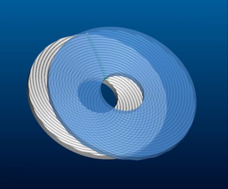
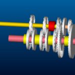
Large number of balls in simultaneous coupling
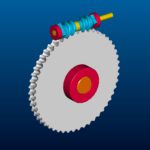
As a consequence of the balls moving away from the wheel perimeter, the coupling path (and time) for each ball becomes longer. This allows for a multiple of balls to be brought in and to put into work simultaneously. In other words, the coupling grooves become longer, they also overlap, and ultimately we have a much larger number of balls such as 10 or even 20 simultaneously coupling the two wheels together – compared to a contact factor of maximum about 3 for conventional gears. Figure 2 below illustrates this feature.
Very high gearing ratios, very small centre distances
Furthermore, as we know in the case of conventional toothed gears, the relationship between tooth size and tooth number, wheel perimeter and gearing ratio resulted in a minimum tooth number or alternatively a maximum gearing ratio. Similarly, this imposed a constraint on the minimum centre distance too. This is not case for sincroll gears. The fact that we can move the balls away from the perimeter makes it possible to produce much higher gearing ratios and also much smaller centre distances than before.
Other features
It is interesting to note that the relative direction of rotation for the two wheels: same or opposite, is an arbitrary input parameter in our design and the only difference between the two cases will be the patterns of the grooves on the two wheels – otherwise the two problems are solved with a pair of similarly overlapping wheels working just the same.
Another peculiar feature is that since the balls are independent elements of the system they can also be manipulated independently – for example, when they are in recirculation outside of the coupling zone – such as cooled, lubricated, monitored, exchanged etc. Also, the balls can be of different material type than the wheels such as ceramics or plastics or perhaps made of electrically insulating material if that might be of an advantage.
Fundamental Law of Gearing still applicable
Also note, the ball gear system while very a different construction and kinematics is still a gear, and as such, it has to satisfy the Fundamental Law of Gearing. That is, in order to have a fixed gearing ratio, the force vector that is normal to the contact surfaces at the contact point has to pass through a fixed point the entire time. This continues to be true in our case too even though the action line is not a straight line here any more, as it was for conventional involute gears, but points from the balls’ instantaneous position on their curved trajectory to the fixed point. Also note that the direction of the force vector may change when we change the size of the ball trajectory as discussed above – still, passing through the same fixed point constantly.
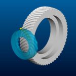
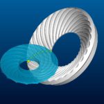
All above applicable for angular gears too
Note, all these considerations above are applicable not only for parallel but also angled axes except that in the latter case the wheels’ overlapping surfaces are not planar surfaces any more. They are overlapping surfaces nevertheless, parallel to each other of course with the grooves facing each other still, and linked together by the balls rolling along the grooves. Two examples are shown in Figure 3.

Dynamics
Bearings for gearing
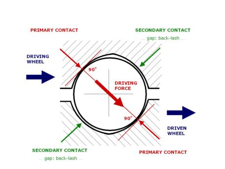
Imposing the requirement of pure rolling of the balls is equivalent to saying that the direction of the driving force must always pass through the centre point of the ball, as shown in Figure 4 below. The cross sectional profile and the pure rolling of the ball for sincroll gears as shown in this Figure is exactly the same as that for ball bearings. The balls see the same local environment where they operate independent of whether they are in a ball bearing or a sincroll gear. This is a quite important observation because it means that any features of sincroll gears that arise from the local contact between the balls and the wheels will be very similar to those of ball bearings. These include manufacturing issues such as material types, tolerances, surface treatment and hardness, surface quality, also operational issues like lubrication and maintenance as well as performance issues like torque capacity, Hertzian stress, noise and lifetime.
One can say that sincroll gears are effectively ball bearings used for a gearing function: inside a bearing, outside a gear.
No back-lash
In order to understand one particular feature of sincroll gears the cross sectional profile in Figure 4 comes very handy – and that is back-lash and its elimination. It is apparent in Figure 4 that back-lash can be eliminated practically fully by introducing four contact points in the system – just like in ball bearings. In contrast to conventional gears, eliminating back-lash in our case will not increase the probability of jamming significantly. In fact, according to our prototype tests, not even energy efficiency will be affected significantly – we tested a drop in efficiency of only 2% as a result of introducing four contact points and eliminating back-lash. In Figure 5 we show selected examples for possible sincroll gear designs illustrating the large variety of gears that can be made using our framework and underscoring the universal nature of the technology. These include rotary-to-rotary gears of various axes angles and offsets as well as various types of rotary-to-linear and linear-to-rotary gears.
Advantages
A summary of potential advantages of sincroll gears is as follows:
- very high dynamic efficiency due to pure rolling, thus very little abrasion and long life
- very high static efficiency, thus no sticking effect, excellent stop/go operation, easy startup
- efficiency substantially independent of gear geometry, axes angles, gearing ratios
- very high precision movement due to many balls in simultaneous coupling, no back-lash
- robust under manufacturing imprecision and pre-loading due to rolling ball-wheel contact
- no (minimal) lubrication, robust under shocks and temperature changes, reliable balls can be manipulated e.g. cooled/lubricated, exchanged, real time in recirculation path
- freedom and flexibility in geometric construction and packaging, large variety of solutions
- very high gearing ratios in one stage, very small centre distances
- no minimum groove (i.e. “tooth”) number due to high contact factor and long contact path
- unconventional solutions e.g.as variable wheel size under the same ratio and vice versa
- arbitrary (i.e. same or different) directions of the input/output rotations
- rotational movement input producing alternating movement output.
Prototype tests
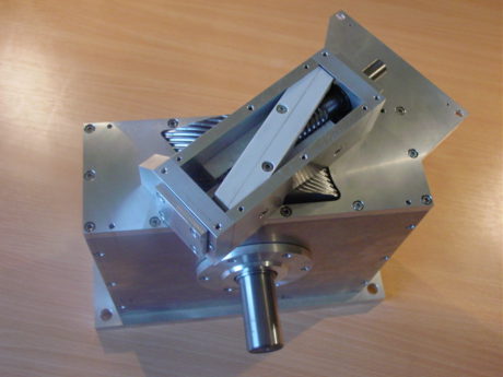
Besides numerous experiments with various models and prototypes, two major prototype tests have been performed. One, at the Technical University of Budapest, on a prototype of gearing ratio 10 with offset 45-degree axes (22 balls in coupling) as shown in Figure 6 and another at the Technical University of Kaiserslautern on a prototype of gearing ratio 10 with offset 90-degree axes (6 balls in coupling) as shown in Figure 7.
Test results proved:
- concept operational, lifetime only about 100 hours so far
- dynamic efficiency 94-98% and static efficiency over 98%
- back-lash elimination workable: resulting efficiency drop of about 2%.
Fig. 7 – TU Kaiserslautern prototype.
Market response and customer projects so far
An extensive network of over 1000 companies has been developed. The market response has been extremely positive showing strong interest and a willingness to communicate but at the same time also quite risk averse. Over 50 design projects have been made on customer request, all for prominent names in their fields, including:
- 9 German, 2 Austrian, 1 British and 1 Hungarian automotive company
- a top Formula-1 team
- a German and a Dutch truck company
- a Croatian electric supercar company
- 3 US, 2 German, 1 British and 1 French aerospace company
- a Swedish, a German and a Hungarian ball bearings/screw company
- an Italian and a Japanese bicycle company
- a German construction company
- a Danish wind turbine maker and 6 German gear makers
- 3 German and 4 Swiss machine tool companies
- a German and an Austrian railway company
- 3 Swiss watch companies.
As an example for an automotive project, we show in Figure 8 below two solutions for a complex car transmission system of 6 forward and 1 reverse shifts, all constructed using sincroll gears. Hybrid systems combining involute and sincroll gears can also be considered making use of the advantages of either technologies depending on the varying requirements in the different gear shifts. As one particular advantage, besides high efficiency and no back-lash etc, it is worth mentioning that sincroll gears can produce the reverse shift in the system using only one pair of wheels. Unlike for conventional technologies there is no need for a third wheel to change the direction of rotation of the wheels in our case because the two wheels can be designed to turn in either direction arbitrarily.
 Road ahead
Taking into account the feedback from the market we are working along two main avenues in our R&D. One, to strengthen the technical capabilities of our technology by improving technical performance such as load capacity, lifetime, reliability and other features. This we believe will reduce technology risk significantly and facilitate the initiation of common development projects with our customers. Number two, we constantly look for the most optimal applications for our technology that promise the easiest entries to particular markets and offer there the largest competitive advantages. Regarding both avenues we see plenty of opportunities for our technology due to the apparently strong technical advantages and the large number of potential applications in a wide variety of markets. www.sincroll.com


