
– Andrea Cadeddu
Department of Engineering Applied to Machines
Cagliari University
In this article, we describe the operation and the applications of compressed air bearings for the handling of loads, in particular the types, their functions, advantages and benefits for the handling of loads in small, medium and big enterprises, including almost all sectors of engineering, metallurgy and steel industry.
Pneumatics is a science that finds large applications not only in the industrial automation field but also in several industrial processes, like for instance in the case of lifting and manual handling of loads with the aid of compressed air, which in several cases proves to be more performing than the hydraulic oil one, whose operation, besides involving higher power consumptions, is strongly influenced by the oil viscosity.
We mention here two of the most used systems in the manual handling of loads, with the aid of compressed air:
- Displacement of loads by means of pneumatic handlers;
- Displacement of loads by means of air bearing supports, which will be treated in the following article in more specific manner.
Handling of loads by pneumatic handlers
Description of the process, use and application
Pneumatic handlers are used to lift or “to handle” loads up to 1 ton but their use is more frequent for small loads and connected with the requirement of reducing the risks of back-lumbar injuries during the lifting phase performed by the worker, in compliance with what provided for by the Legislative Decree 81 dated 09/04/2008, which rules health and safety in workplaces.
We can affirm that they are actually mandatory and always present inside whatever firm or factory, since the regulation establishes 25 kg for adult men and 20 kg for adult women as the maximum weight they can lift; the risk is assessed with two methods:
- NIOSH method for the lifting index in the manual handling of loads;
- Snook and Ciriello method for the activities of pushing, towing and transport of loads on flat surfaces;
These regulations concern the activities involving the manual handling of loads with the risks, moreover, of back-lumbar injuries for workers.
The workplace must be equipped with appropriate means to reduce the risks deriving from the manual handling of loads.
When it is possible to avoid the manual handling (lifting, pushing, towing and transport) of loads, the employer must provide workers with suitable means for reducing the risks deriving from these operations; therefore, with the aid of pneumatics, mechanical arms and suckers powered by compressed air, which correspond to the most used typology, they replace human “arms “, especially when the weight to be lifted exceeds what the regulation reports, but also when the weight decreases under 20-25 kg (fig.1 and 2).
The installation of mechanic arms also to lift weights under 25 kg allows, in fact:
- Notably reducing the risk and the number of accidents;
- Eliminating the risk of lumbar trauma for the back;
- Carrying out a faster work;
- Reducing the physical labour;
- Thanks to the user-friendliness of pneumatic systems, employing “unsuitable” personnel for the manual handling.
Handling of loads by means of compressed air bearings
Process description
These systems use the efficiency of the air bearing to lift and to displace loads of whatever size, shape or weight; they can be positioned under a load of any shape and they either lift or support, as needed.
Unlike wheeled systems, which oppose resistance when we change direction, thanks to the air bearing, they are omnidirectional and no additional force is needed to change direction, apart from the worker’s.
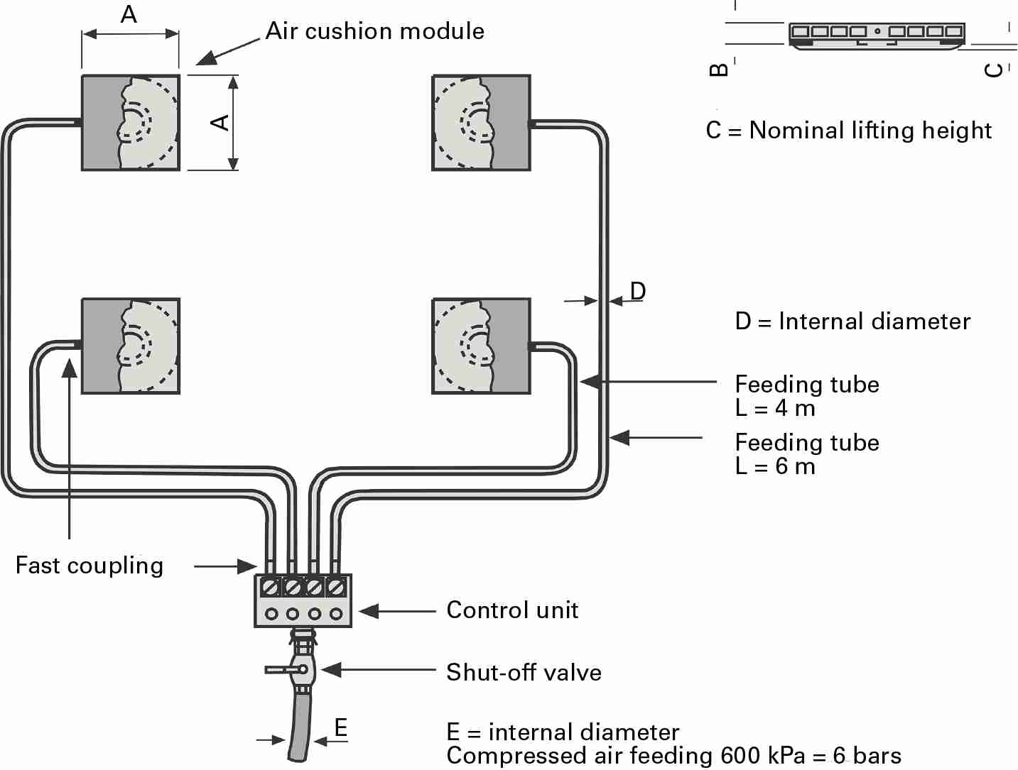
Setting aside the physical principles of the process that refer to the base fluid dynamics principles and whose treatment is not encompassed in this article, we can generally schematize the process according to what exposed in figure 3, representing the typology with air bearing modules.
As we can notice, air bearing modules, which in the example are 4, are connected by a set of tubes with a control unit, in its turn linked with an air net that is part of a compressed air tank or of a compressor; this results in very simple scheme and system in itself, easily constructed on the spot.
After opening the valve of the compressed air tank or setting a compressor in operation, you gradually act on the valves equipping the control panel (or control unit) until when the air bearing modules lift the load from the ground, thus creating a thin air film under them. The load “fluctuates” on the air layer, in absence of friction (approximate coefficient 0.002) and it is easily manoeuvrable and positionable.
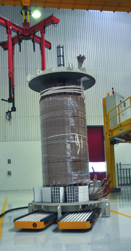
Their use concerns whatever sector, for instance to displace big diesel motors of ships and big paper or metal coils or electric cables, harbour containers, big electric transformers, components of nuclear power plants, tanks and missiles; in the building industry to position big prefabricated structures and everything “big” may still exist.
Typologies of plants with compressed air bearings
The most used systems can be included in 3 typologies:
- Modular systems;
- Standard beam systems;
- Specific powered shuttles for coils;
Modular systems
Their operation principle is shown in fig. 3 and they are perhaps the most diffused systems since they are used for challenging displacements like those of very heavy loads, positioning and handling in narrow spaces and delicate or high-safety displacements, like for instance engines of ships and rail cars, placing them in a very precise position but especially drastically reducing the effort of the worker who handles the load thanks to the almost absence of friction between load and ground.
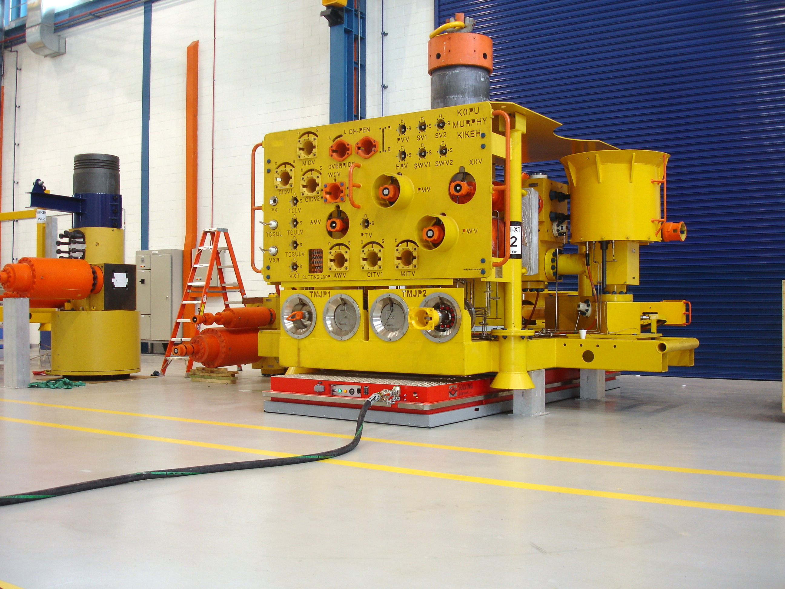
The study of their shape facilitates their easy introduction under the load to be lifted; the arrangement under the load to be lifted is carried out by keeping them as distant as possible one another, in order to subdivide the weight equally (fig. 4).
The “power game” of modules is represented by the capacity or “lift” of each one that generally varies from 3 up to 160 tons, therefore it is theoretically possible to displace very heavy loads, like for instance 1000 tons, using several modules.
One of the limits of these systems is probably represented by the floor; in fact, besides being constituted by a compression-resistant material, it must be not only in good preservation condition but also as smooth and polished as possible; in zones of the floor where discontinuities are present, like linear expansion joints or small cracks, the remedy consists of particular carpets or adhesive belts that make the surface contiguous.
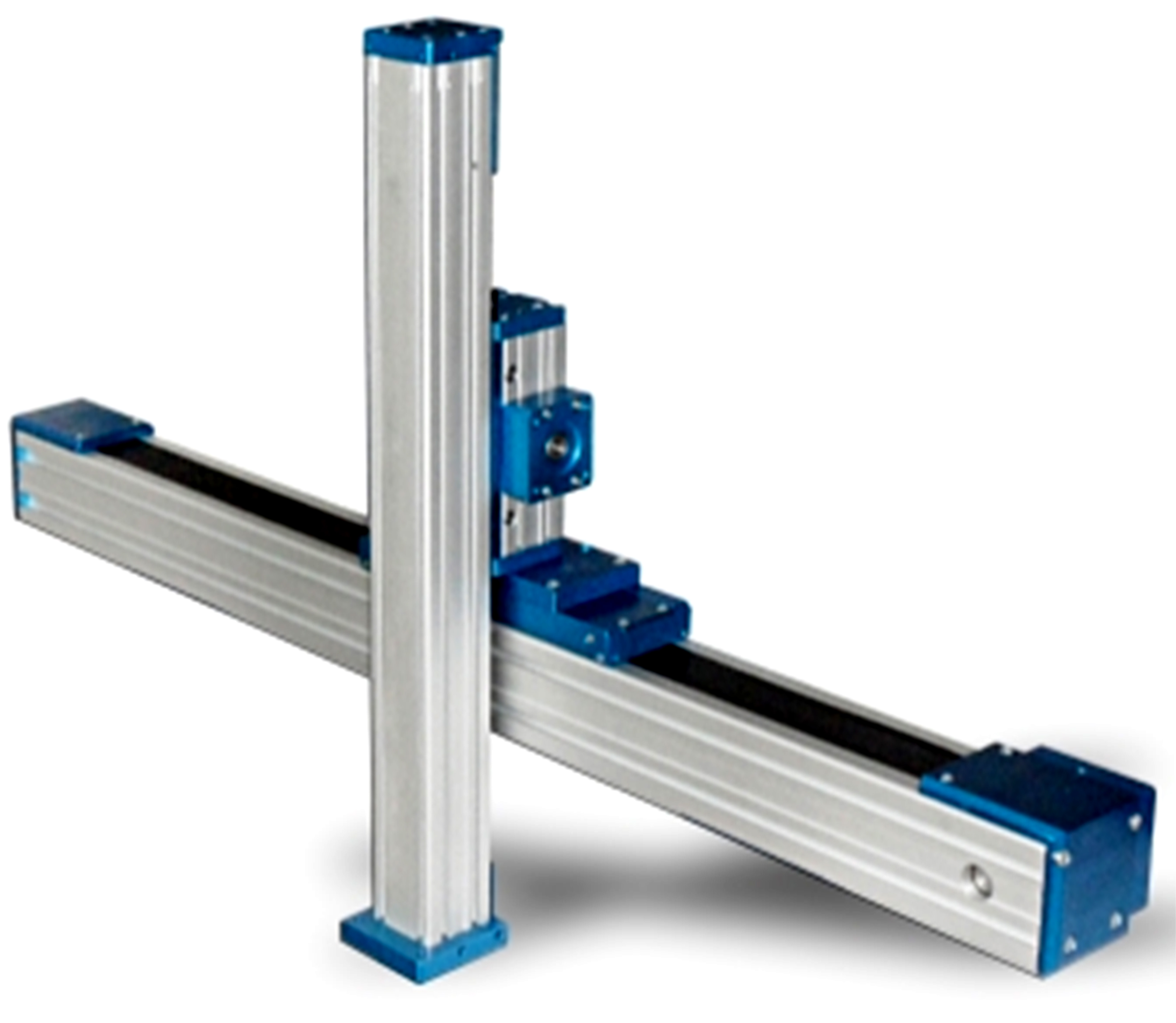
Beam systems
They are actually constituted by a sort of carriages with a shape resembling transpallets; their advantage, in comparison with the modular system, is the speed of positioning under the load to be lifted. They are frequently used for lifting machines, vehicles, steel items, seats and heavy components in motion in factories and workshops (fig. 5).
Beam systems are generally used in pairs and each beam is formed by a subtle steel structure with two air bearings. Under the load are positioned two or three beams, each equipped with control panel. You connect the compressed air with the control panel and a thin air film is formed under the bearing, where the load floats almost frictionless.
The load is handled manually or with the aid of towing units.
Specific powered shuttles for coils;
Likewise the above-described beam systems, they are actually constituted by carriages with a shape resembling transpallets and they feature some wings that suit the cylindrical shape of the coil; the speed of positioning under the load to be lifted is fast and it is an optimal equipment in all industries producing “discontinuous” shapes, like cylindrical or circular ones.
Conclusions
Why using compressed air, what are the advantages for the manual handling of loads?
The compressed air is a source of not dangerous and clean energy source, nowadays available in all industrial realities and besides today it is consolidated both for the development of the driving force and the managerial logic. Its components, now standardized and certified, are highly reliable and easily maintained even in the harshest environment; besides, compared to electronics, are not affected by “infant mortality”.Finally, since pneumatics is a traditional technology, the maintenance personnel is generally skilled in it and nowadays the compressed air offers the best fluidity in the load balancing effect.


