
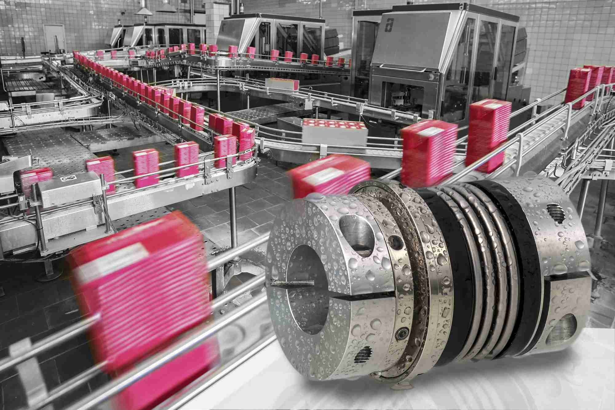
Bellows couplings are used where precise rotation, high speeds, and dynamic motion must be transmitted. They exhibit zero backlash and a high level of torsional stiffness, offering distinct performance advantages. Their successful implementation, however, requires proper sizing and handling. R+W’s wide range of high-precision bellows couplings, combined with the ability to create effective made-to-measure applications, ensure excellent results for every requirement.
With some exceptions, most bellows used in shaft coupling applications are made from one or more layers of high grade stainless steel sheet, formed and plasma-welded into a seamless tube, and either rolled or hydroformed to produce the deep corrugations (convolutions) which provide its flexibility. The resulting shape is one which is continuously symmetrical, and highly rigid about its rotational axis, while remaining flexible across all three other axes: parallel, angular and axial. Bellows are joined to the hubs by crimping, welding, or bonding. The end hubs and bellows are mounted onto a single mandrel during assembly, with the ends of the mandrel matching the respective bore diameters of the coupling hubs, guaranteeing concentricity. Bonding came into common practice in the late 1980’s, with the advantage being that it allows for the bellows to be floated between the two hubs, free of stress, until the bonding agent cures. This helps to avoid deformation or stress concentration on the bellows, ensuring that it will run smoothly, with consistent output rotation, once installed. In cases where the coupling will be deployed in corrosive environments or be subjected to temperature extremes, either of which can cause the bond to break down, welded bellows-hub connections are preferred.
Bellows couplings are often selected in place of low cost jaw couplings and disc pack couplings by engineers looking to benefit from their well-documented performance advantages. But they will only work well to those ends if shaft misalignment is addressed. Bellows couplings do not typically handle as much misalignment as traditional flexible couplings, but impart relatively low restoring loads onto adjacent shafts and bearings while compensating for the levels of misalignment they are designed to handle. When properly aligned, typically within 0.2-0.4mm parallel, they are fatigue resistant for an infinite service life, with no maintenance required. But if shaft alignment, especially parallel misalignment, is not considered before replacing other types of couplings with bellows couplings, failures can result. While reduced misalignment ratings can be viewed as a drawback, most experts in power transmission would agree that, regardless of the coupling style being used, proper shaft alignment always results in longer life and smoother rotation for all drive line components. Bellows couplings are not typically intended to compensate for gross offsets (though special high misalignment versions do exist) but rather to mitigate restoring forces between reasonably well aligned shafts, while also remaining as stiff as possible in rotation.
Main applications
Bellows couplings are mainly used in applications with the following characteristics:
- High precision positioning: When it comes to rotational positioning the benefits of zero backlash and high torsional stiffness are normally fairly obvious. Lost motion from backlash is eliminated, and torsional deflection (twisting) between the input and the output of the coupling is minimized. Bellows couplings generally have the highest torsional stiffness of commercially available flexible shaft couplings. Another benefit results from its continuous symmetry. Most flexible power transmission elements have some kind of asymmetry, which means that, due to misalignment, the coupling is under different stress profiles at different points around a single rotation. To varying degrees they build up and release energy while rotating under misalignment, and have slight variations in their output speeds. In most applications this is scarcely noticeable. However in precision applications, where positional accuracy is to be optimized, the continuous symmetry of the bellows offers a measurable advantage.
- Highly dynamic motion: Bellows couplings are also well suited to highly dynamic motion profiles. The high torsional stiffness translates into shorter settling times when loads are abruptly started, stopped, and reversed. As the weak link in most direct drive systems, the flexible coupling normally determines the stiffness of the entire drive axis. A coupling with higher torsional stiffness increases system natural frequency and decreases oscillation amplitude, enabling faster moves. When properly sized, bellows couplings allow designers to increase cycle rates in camming and reversing applications. Since bellows couplings also tend to be offered in low mass moment of inertia configurations, they also play their part in minimizing load inertia.
- High rotational velocity: For high rotational speeds, the same geometric characteristics come into play. Light weight, continuous symmetry, and uniform stress distribution all lend themselves to smooth, stable running at high speeds. Standard bellows couplings are rated to run at 10,000 rpm, with the limiting factor being the clamping hubs. Much higher speeds become possible through balancing of the coupling assembly. In some instances, bellows couplings can be made to run at speeds in excess of 100,000 rpm.
- Resistance to extreme temperatures: When machinery will be subjected to extreme temperatures, metallic couplings are normally favored over elastomeric couplings, as their mechanical properties remain largely unchanged, even over a wide range of temperatures. When bonded joints are replaced with welded joints, the bellows coupling meets this requirement. The unique advantage of bellows couplings is that, unlike other types of maintenance free metallic couplings (i.e. flexible disc couplings), bellows couplings have a high tolerance for axial movement. This allows them to absorb the axial movement which can result from thermal growth in drive shafting and other structural changes in the framework of the machine. For this reason, high torque bellows couplings are often used in drive shaft configurations for heavy equipment installed in remote areas.
Elastomer couplings Series EK from 0,5 – 25.000 Nm: precise, sturdy and backlash-free, for vibration damping.

Sizing
Bellows coupling sizing is generally guided by DIN 740, which is comprised of four different formulas:
- Selection according to torque: Because they are normally installed in servo drive systems, bellows couplings are sized for the peak torque to be regularly transmitted. The peak torque of the application should not exceed the rated torque of the coupling. The following calculation provides a safe approximation of the minimum required coupling size, and allows for the maximum speed and misalignment to exist in the application.
- Selection according to acceleration torque: A more detailed calculation takes acceleration and the driving and driven moments of inertia into account. Shock / load factors ranging from 1-4 are applied, depending on the dynamics of the application. Factors in the range of 3-4 are normal for highly dyanamic applications with multiple indexes per second or frequent load reversals. A favorable driving to driven inertia ratio diminishes the effect of the shock / load factor in the sizing calculation.
- Selection according to torsional deflection: Since bellows couplings are often applied in situations where positioning accuracy is critical, the following calculation is useful in determining the transmission error as a result of torsional stress.
- Selection according to resonant frequency: There are some rare cases in which the drive can pulse the load in such a way as to excite the natural frequency of the mechanical system. In order to avoid this, the torsional natural frequency of the mechanical system must be significantly higher or lower than that of the excitation frequency of the drive. In the case of torsionally stiff bellows couplings, the torsional natural frequency should generally be significantly higher than the oscillation frequency from the motor. The torsional stiffness of the coupling generally determines the torsional natural frequency of the complete system. Therefore the torsional stiffness of the coupling becomes a critical factor in determining the natural frequency of the mechanical system. In the following two mass system calculation, a value of fe ≥ 2fer helps to ensure adequate stiffness for smooth, stable running.
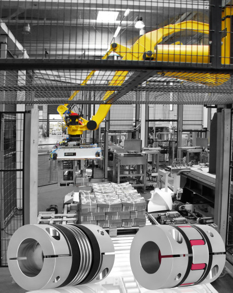
Fig3
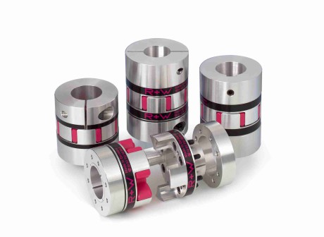
Bellows couplings Series BK; they are precise, zero-backlash and well suited to highly dynamic motion.

Installation and handling
Shaft alignment: When properly aligned, adequately sized bellows couplings are fatigue resistant for a theoretically infinite service life. Many types of commercial electromechanical equipment have features included in the frames to help guarantee precision alignment during installation. Most commonly these are round centering pilots on motors, gearboxes and linear actuators, which are of a precise diameter, and highly concentric to their respective shafts and bearing journals. Driving equipment typically has a male centering pilot, and driven equipment typically has a matching female centering pilot. As the frames are bolted together, these centering pilots hold everything within sufficient alignment, and the bellows coupling compensates for the slight misalignment that remains. In cases where the coupled equipment will be mounted to separate surfaces without integral features to help guarantee alignment, additional steps must be taken. Alignment between shafts must be checked with dial indicators or laser alignment tools, and adjustments made accordingly until the target alignment level has been reached. In those cases, bellows couplings with fully split clamping hubs are often used, since they can be installed laterally after the shafts have been aligned. In cases where precision shaft alignment is simply not practical, special high misalignment bellows couplings are available which can accommodate a parallel shaft misalignment of up to 1mm.
Shaft locking: Because they tend to be used in high performance applications, most bellows couplings are mounted to their respective shafts and flanges by frictional clamping systems. This helps to avoid the backlash and stress concentrations which result from connections made by keyway only – though in many cases keyways are still broached into the clamping hubs for a positive form fit connection. To help guarantee good shaft locking, most precision coupling bores are made to a diameter tolerance of ISO H7, which allows for zero undersizing, and oversizing by anywhere from 0.01 to 0.04mm, with the tolerance range increasing with larger shaft diameters. In turn, most manufacturers of motors, gearboxes, and linear actuators make the shafts to a diameter tolerance which allows for zero oversizing and slight undersizing. This helps to create a slip fit between the shafts and couplings during installation. When installing couplings with clamping systems, it is important to follow the installation guidelines for screw strength and tightening torque values. Most bellows couplings use high grade screws, allowing for the maximum torque and tension to be applied, helping to guarantee a secure lock onto the shaft.
Mounting options: Over the past three decades a very wide variety of sizes and mounting attachments have been developed for bellows couplings. For small and medium sizes, the most common drive attachment is the single screw clamping collar. This allows for quick and easy installation with zero backlash. For larger sizes, typically transmitting torque levels of 1,000 Nm or more, conical clamping bushings become more common, as they provide larger clamping pressure between the shaft and hub. Flanges are another popular way of attaching bellows couplings, since they tend to be very compact, and also allow for good stress distribution and a high level of frictional holding force.
For transmitting dynamic precision motion between two fixed shafts, flexible bellows couplings offer the benefits of high torsional stiffness, low moment of inertia, continuous symmetry, and low reaction forces under slight misalignment. When sizing, misalignment tolerances, and proper handling are addressed, they can help machines run faster and more accurately.
For further information on R+W’s complete range of bellows couplings and other products: http://www.rw-couplings.com


Yes! Of course, most bellows couplings use a stainless steel tube that has been hydro formed to create deep corrugations to make them flexible across axial, angular and parallel shaft misalignment’s.