
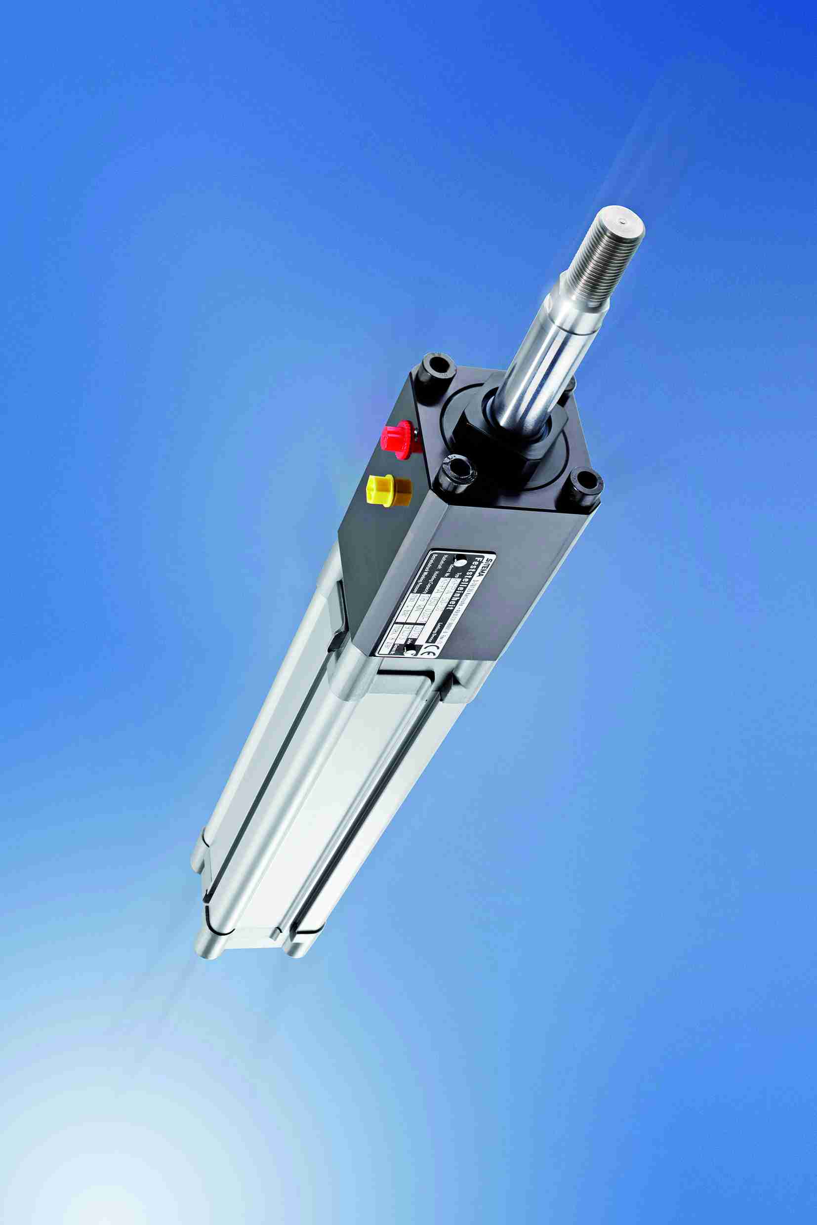
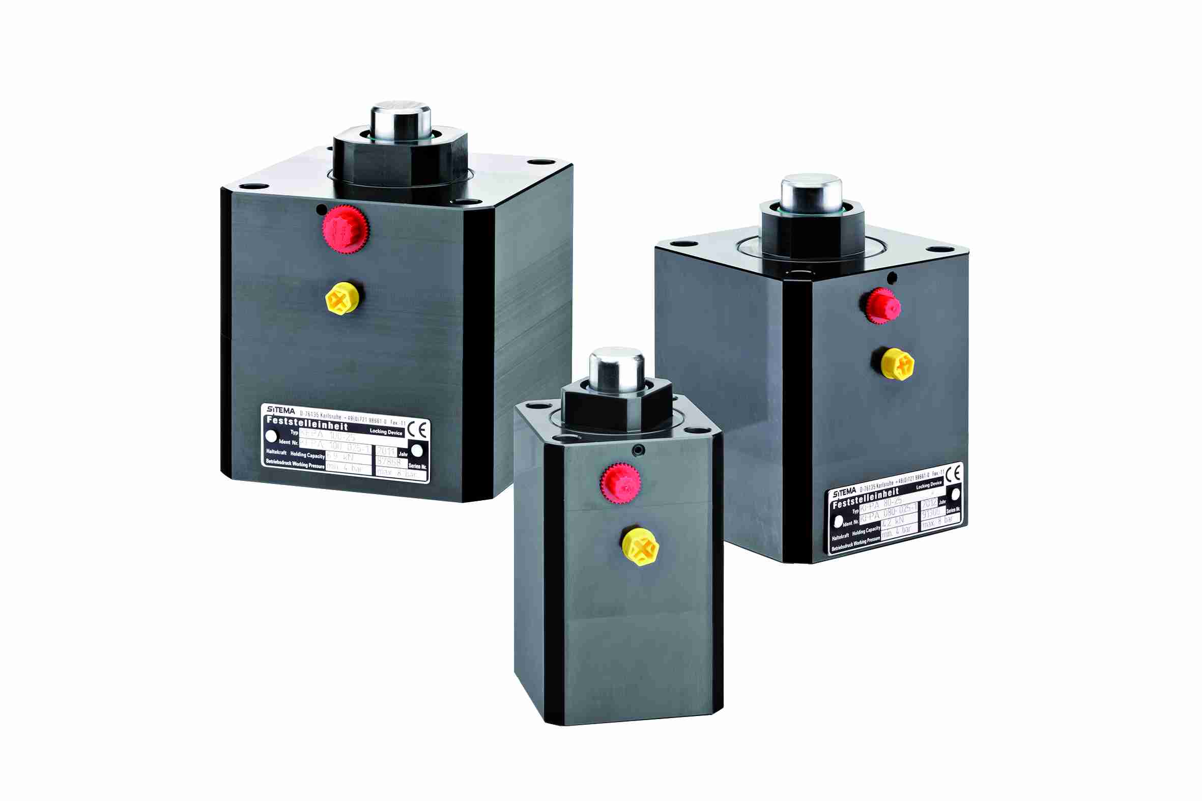
The bidirectional locking devices KFPA developed by Sitema are a compact solution for the safe locking, in whatever point of the stroke, of piston rods in standard cylinders complying with the ISO 15552 regulation.
It is named TI-F22 the bidirectional locking device KFPA implemented by Sitema, German company specialized in the design and production of locking units and linear brakes on round bars. This system adjustable in continuous, used for the safe locking in whatever point of the stroke of the cylinder rod, can be easily mounted on cylinders conforming to the ISO 15552 regulation or on a separate rod. The new range of locking systems is available in versions for cylinders with diameter starting from 16 millimetres up to reaching 40 millimetres. Forces are generated by the standard spring holding system by Sitema, which generates holding forces reaching 10.9 KN (more than one ton), while the release is actuated by the available pneumatic pressure.
The KFPA locking device is generally fixed on the cylinder head, but a version for application without cylinder is provided, too. A variant devised for the cases in which the locking device is mounted on a separate rod, which must be used only in combination with the related centring ring prearranged by Sitema.
The choice of sizes and the execution
In the KFPA TI-F22 locking device the axial backlash is one tenth of millimetre in both loading directions. Sitema has prearranged a selection table to identify the right sizes for the choice of the locking model and in particular of the nominal holding force of the respective structural size, which must be higher than the axial force acting on the rod. Besides, if masses that move rapidly must be locked or braked, or if dynamic impact forces are present, the nominal holding force must be higher by one safety factor than the weight force to be locked, to be established from time to time according to the plant requisites (but generally not inferior to 1.5).
Concerning the rod implementation and fixing, the regular operation of the KFPA locking device is exclusively granted when we use a locking rod in conformity with the following requisites: tolerance range ISO f7 (or h6), surface roughness with Rz= 1 up to 4 µm, hardened rod surface (at least RC 56) and lead-in chamfer min. 3×20° (rounded). The producer suggests further hard chrome plating 20 ±10 μm, 800 – 1000 HV.
Suitable rods
Sitema mentions two examples of available rods suitable for the use with the KFPA TI-F22 locking system:
- Piston rods, with hard chromium-plating (tolerance f7). Base material: yield strength min. 580 N/mm²; Induction hardening HRC 56 – 64 / min. 1 mm depth; hard chrome plating: 800-1100 HV min. 13 μm depth; surface finish: RA 0.15 – 0.25
- Shafts for linear ball bearings (tolerance h6). Induction hardening HRC > 60; Surface finish: RA 0.15 – 0.25
It is also worth underlining that the actual holding force of the bidirectional locking unit KFPA is higher than the nominal holding force indicated in data sheets and drawings, but it will not be higher than twice its value. Therefore, all fixation elements carrying the load (rod, its attachment …) must be dimensioned at least 2x the nominal force (F). It is in fact advisable to bear in mind that in dynamic loads the full holding force can occur (2 x F). Only if it is certain that the maximum loads are effectively smaller, the fixing can be dimensioned also according to such values. Generally, the basic rod material is requested to have sufficient yield. In case of compression-loaded rods, sufficient buckling resistance must be assured. Concerning the fluid, the compressed air must be dry and filtered. Sitema suggests the one included in 5-4-5 class as per ISO 85731-1.
The operating principle
After examining the specific characteristics of KFPA TI-F22, we are going to see in detail what are the general operation principles of the bidirectional locking devices produced by Sitema in a range of models that include versions hydraulically and pneumatically actuated (as in the example above described), with the holding by means of springs and the release through pressure (it is the case of the new series), with the holding and release through pressure and so on.
These devices lock the rod without modifying their position and absorb the axial forces in both directions. Depending on the type, the opening is assured by a hydraulic or pneumatic pressure. The holding force is produced by the elasticity of springs or by the hydraulic pressure. The locking system is composed by a locking bush with outer cone and by a locking sleeve with inner cone. The bush is axially fixed in the carter and moves only radially, therefore you can obtain an almost backlash-free locking. The locking sleeve is guided in the carter and it is pressed in axial direction by the bush for the locking. The locking force is produced by the pressure or by the springs and reinforced by the conical surfaces (and/or inclined plans). The locking head is so lifted, resulting in a defined air gap, so that the rod slides without any difficulty.
The locking unit receives forces in both directions. When it is overloaded, the rod slides. This fact does not generally cause damages, nevertheless in design and use phase recurrent overloads (braking) must be avoided, unless the materials of the bush and of the locking rod are adequate. On the contrary, depending on forces, on the sliding speed and on the rod quality, it is not possible to exclude gripping problems.
Through springs or pressure
As mentioned before, the bidirectional locking systems by Sitema are available in versions with locking by means of springs and release through pressure (it is the case of the KFP series, specifically treated in this article); KFH with maximum rod diameters of 300 mm; KFHS certified EN 693 for applications on presses, KFHR for wet and cold environments, KFHL certified Lloyd for naval applications etc.) and in versions with pressure locking and release (KB and KBP series). In the first case the locking unit is not under pressure, the rod is locked by the elastic reaction and can transmit the whole nominal holding force. During every operational cycle, the 3/2 way valve is actuated and then it releases the locking unit. In all other operational conditions (including also the power failure, the emergency stop and so on) the locking unit holds the rod and breaks the load. The latter is secured also when the pressure line breaks. To prevent possible problems, the rod shall not be driven unless the proximity switch indicates the signal “released “.
In the case of the KB/KBP series, the rod is instead locked by the pressure, with holding force widely proportional to the applied pressure. The valve position change releases the locking. To prevent possible problems, the rod shall not be driven unless the proximity switch indicates the signal “released ” (www.sitema.com/it).


