
Some examples of pneumatics applications in gripping systems for industrial use. a constantly expanding sector due to manufacturing companies that release different and often complex shapes on the market.
Andrea Cadeddu
Today, perhaps more than ever, industrial automation plays a fundamental role in the progress of several existing companies and, at the same time, it boosts the growth of new ones. In general, for industrial automation and non-, we mean that particular technology that allows replacing man with machines, not only to perform physical operations, also prescribed by specific laws on the manual handling of loads, but also to decide rationally and smartly what operations must be carried out and according to what modalities. It is always up to man to decide which operations the machine must execute whereas human operators’ work is replaced by robots, i.e. flexible and programmable mechanical structures.
Different types of handlers
On trade, there are different kinds of handlers, which differ by type and number of joints, for instance: Cartesian handler, gantry handler; cylindrical and spherical handler; SCARA or anthropomorphic handler. The handler features on the terminal part a mechanical wrist, on which are installed terminal organs to allow the handling of objects or to execute some operations on workpieces. Terminal organs are subdivided into two categories: work tools and gripping organs or grippers. Tools are devices ideated to carry out a determinate function, for instance standard machining are welding, painting, drilling and milling, laser or water jet cutting, bonding, wiring, finishing and screwing. In this article, we are not treating tools, which are an important link in industrial applications whereas we are dealing with gripping systems and especially those that exploit pneumatics as operation principle.
Gripping systems
Gripping organs for industrial handlers have the task of grasping objects and permitting a displacement, a machining or an assembling operation. As described, there are several varieties of grippers, each of them with highlights and drawbacks, suitable for each application. We are hereunder listing the most common typologies, giving up the thorough analysis of micro-grippers and grippers of special nature.
Main gripping systems for automation must satisfy the following functions:
- temporarily granting a defined position and orientation of the item with regard to a reference system;
- keeping determinate forces and moments in static or dynamic conditions;
- permitting the variation of position and orientation of the object in relation to a reference system;
- allowing specific technical operations demanded by the particular application.
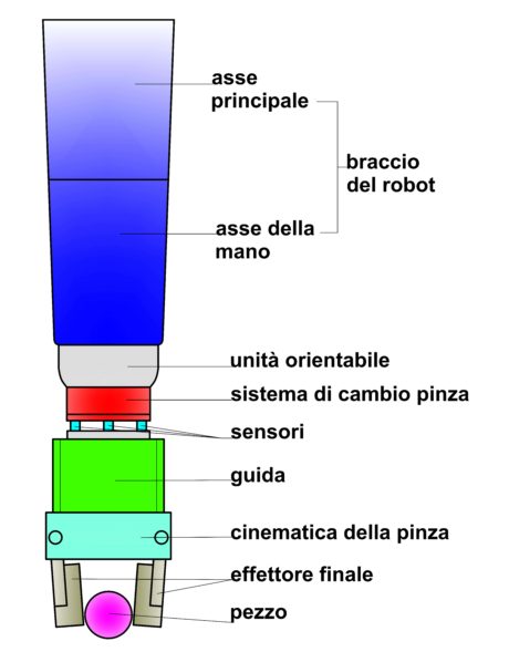
The primary application fields are the following: assembling, mounting or packaging lines; industrial robotics (gripping and handling of objects); service robotics (anthropomorphic grippers); Numerical Control machines (use of tools); object loading and unloading systems; remotely controlled handlers (medical field, aerospace, marine); The components of an end-effector are represented according to a standard scheme in fig. 1.
Typologies of gripping organs
Gripping organs can be classified in four main categories, listed hereunder according to the usual English terminology:
impactive: a mechanical force is directly impressed on the object from one or more directions;
ingressive: the gripping occurs through the insertion of the gripping organ into the object, through one or more surfaces;
astrictive: a force or an attractive field binds the object, allowing its gripping;
congiuntive: the object support is accomplished through a unidirectional force developed after the direct non-impactive contact.
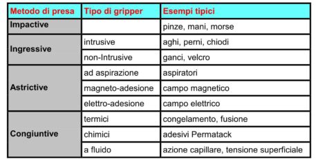
The vast majority of industrial grippers are of Impactive or Astrictive type (with suction or electromagnetic) due to their versatility and lower cost. The other typologies are mainly used in very specific sectors, like food, textile, electronic or semiconductor industry. The category of Ingressive grippers is further split into intrusive and non-intrusive organs; the first penetrate through the material whereas the second just join the piece itself or lock it. In the table represented in fig. 2 there are some examples of grippers listed by applicative typology. There are other categories of grippers used on particular applications, such as limited-contact or contactless grippers with Bernoulli effect or the sub-family of micro-grippers (piezoelectric).
The astrictive gripper typology stands out for the development of the continuous force without object compression, like for instance the grippers with suction, magnet-adhesive and electro-adhesive.
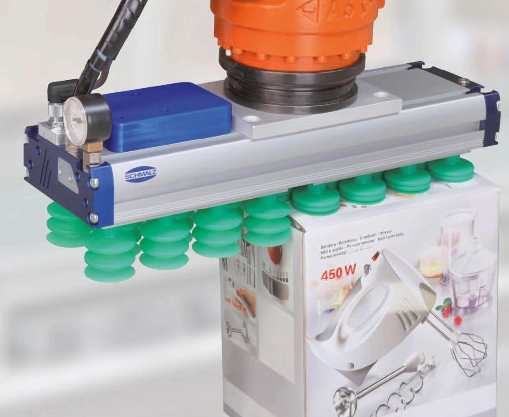
Vacuum suction and vacuum suction cups
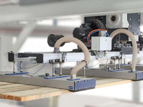
One of the major applications frequently used in industrial plants, and also one of the most ancient, is the vacuum technique. Gripping systems can be classified according to the gripping technique: a typology uses vacuum generators (fig. 3), the other adheres through vacuum suction cups (see opening figure). Gripping systems that exploit the suction “directly” are used to lift big and heavy objects as well as small components, like for instance in the micro-electronics industry. The operation principle is simple, a flexible cap with a particular surface is hermetically compressed on the surface of the object. Vacuum is then generated inside the cap, creating a negative pressure that supplies the necessary force for the item support. The other typology differs from the previous one as vacuum is generated by electro-mechanical devices and the flexible cap of the gripping system in direct contact with the object is called “suction head”, generally made of elastomeric material. In industry, the necessary vacuum for gripping is produced by pneumatic vacuum generators and they are called ejectors; otherwise electric vacuum generators are used and we define them mechanical pumps; in general, the following methods are used: pumps and blowers, Venturi-effect generators (ejectors); bellows and pneumatic cylinders.
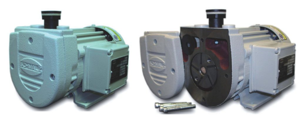
The use of pumps (fig. 4) allows obtaining high vacuum values at low machining costs. They consist of a wheel mounted in eccentric position with sealing slats. The centrifuge force pushes the slats towards the exterior, thus creating some chambers of different sizes. The air expands through the enlargement of chambers and the air pressure decreases and a depression (vacuum) is created. On the contrary, the initial costs for accessories and installations are very high.
Blower generators or vacuum blowers produce low vacuum values, however they are easily controllable and suitable for gripping porous objects; they are used in all those situations where it is necessary to suck and to handle pieces that are very permeable to air, like cardboards, insulating materials, chipboard panels or bags and they assure a high suction of big volumes in very short times.
Venturi-effect generators (ejectors) are easily installed, with low initial costs, they take advantage of not having parts in motion and they can be directly integrated into the gripper. Drawbacks derive from high operational costs owing to the continuous consumption of compressed air. These generators are the most diffused because, by means of a simple valve, you can obtain the object ejection. Besides, it is easy to increase gripping force or safety simply joining more blocks in series or in parallel. Pneumatic gripping systems are used especially for assembling applications. They do not directly depend on a flow of compressed air but they alternatively produce a suction and an ejection according to the piston stroke.
The pressure exerted on the object is given by the ratio between the F retention force and the A active surface. Considering the effects of the gravity “g” and of the robot acceleration “a” on an object with mass “m”, the contact pressure s is obtained through the following equation:
σ = [N/m²]
Concerning a generic suction gripper, the initial static gripping force is approximately calculated by the following formula:
F = (σ0 – σu) × A [N]
Where σ0 is the atmospheric pressure [bar] and su the applied vacuum pressure [bar].
In general, the vacuum values it is possible to produce range from 10% (-0.101 bars) to 90% (-0.912 bars) and reaching negative pressures that exceed 60% is a burdensome implementation. Analysing the phases, once performed the gripping and as soon as the robot starts moving, numerous other secondary effects that represent some losses are involved, like the deformation of the cap, determining a decrease of the effective gripping force.
An assessment of losses and of the effective quantification of retention forces is given by the following formula:
F = (σ0 – σu) × A × n × η × z × + m × g [N]
n coefficient of deformation (0.6 ÷ 0.9)
fs safety coefficient. Typically 2≤ fs ≤3
z number of suction caps
η system efficiency
The gripping force is directly proportional to the active area, which in its turn is function of the cap geometry. The diameter d of a circular suction cap can be approximately calculated by the following equation, assuming a static or slowly variable situation:
d = 11,3 × [mm]
Therefore, we obtain always and exclusively theoretical forces from the calculation of gripping forces.
In practice, there are several decisive factors, like for instance the structural shape of the vacuum suction cup and the surface conformation, as well as the piece stability (deformation).
According to the technical literature, they almost-always refer to specific directives where the minimum safety factor is 1.5; however, it is necessary to consider that the safety factor for the «piece rotation », taking into account the occurrence of overturning moments, must be risen to 2.5 or over.
In vacuum suction cups, the vacuum is created through a compression of the cap, made of soft material, against a smooth or slightly curved surface of the object. Such compression force can be either manual or mechanic, with pneumatic or electric drive. The gripping does not depend on any power supply source and then it is considered always safe, even if eventual pressure losses cannot be compensated. The object is released by a valve on the cap that allows the compensation with the atmospheric pressure (exhaust valve).
Choice of vacuum suction cups
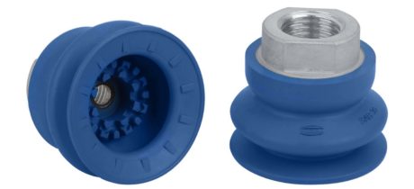
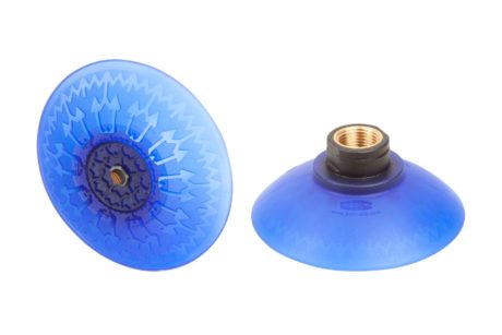
Vacuum suction cups (fig. 5 and 6) are chosen according to the following criteria:
Typology of their use: for instance, the operation on more shifts, expected fatigue life, environment with chemical aggressive agents, temperature and so on;
material: depending on requirements, different materials are available, particularly suitable for smooth, rough or oily surfaces or for highly sensitive pieces; antistatic vacuum suction cups for electronic components, vacuum suction cups that do not leave marks for delicate plastic parts and so on;
surface: depending on the surface shape, vacuum suction cups with specific structural shapes are used. In general, at the time of making the choice of the suitable vacuum suction cup, it is necessary to make a distinction between flat or bellows vacuum suction cups, with different kinds of sealing lips and different structural shapes or geometries.
We thank the company Schmalz S.r.l., with headquarters in Novara (No), which has kindly made available information, technical brochures and photographic material.
In conclusion
The gripping organs that are handled by using the vacuum technique represent an ancient system, therefore tested in time; they offer such safety, cheapness and easy application degrees as to be used in almost all industrial fields. “Gripping means taking”; gripping systems implemented with vacuum suction cups or vacuum area gripping systems constitute an efficacious, safe, user-friendly and cheap system for the handling of the most various materials, assuring an ergonomic work environment and also granting the prevention of osteomuscular diseases of the spine, deriving from the displacement of heavy loads and repeated actions.
[su_box title=”BIBLIOGRAPHY”]· Aut. B. Ferrario, “Introduzione alla tecnologia del vuoto”, II ediz. Pàtron Editore, Bologna, (1999); · Aut. G. Belforte, A. Manuello Bertetto, L. Mazza, “Pneumatica – Corso Completo”, Tecniche Nuove, Milano, (1998); · Aut. G. Belforte, “Manuale di Pneumatica”, II ediz. Tecniche Nuove, Milano, (1998); · Aut. C. Ferraresi, T. Raparelli, “Meccanica Applicata”, III ed. – Clut, Torino, (2007).[/su_box]


