
Lift trucks carry the weight of industry by moving goods from one place to another in distribution, logistics, warehouses and manufacturing. In these environments, reduced operating costs and increased efficiency and productivity can provide businesses with a critical competitive edge. Here Tim Meehan, Lead Systems Engineer at Eaton, introduces a hydraulic hybrid system solution that can help reduce fuel consumption as well as improve CO2 emissions.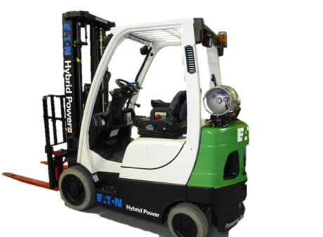
If we were to look at the fuel consumption of a lift truck during a normal working day, it can be astonishing as to how little work gets done in comparison to the fuel energy consumed by the truck. Looking closely, a lot of the fuel is wasted as heat through the engine and inefficiencies of the hydraulics system. In reality, just a small fraction of the fuel energy results in useful work – it is estimated as low as single digits. This is why high efficiency solutions like the Eaton hydraulic hybrid energy recovery system are needed and especially effective for lift trucks.
Duty Cycle
When examining the duty cycle of a vehicle, factors to consider are the operating time, fuel consumption during this period and the number of start/stop and lift/drop cycles. Eaton has over fifteen years of experience investigating duty cycles for several different platforms.
The original focus was on-highway vehicles, such a bin lorries and shuttle buses, which have duty cycles favourable to regenerative braking. In these hybrid energy recovery systems, the main drive line is preserved and a hydraulic hybrid system is added in parallel. As the vehicle slows, energy is captured in the accumulator as compressed gas, which is later released to propel the vehicle forward. These early parallel systems evolved to more advanced architectures, with more advanced controls and more integration with the engine. The hydraulic hybrid driveline also replaced the original mechanical driveline; this is termed as a ‘series’ hydraulic hybrid system.
Hydraulic Hybrid Lift Truck
To demonstrate how far hydraulic hybrid systems have advanced over the years, Eaton purchased a conventional 2.5 tonne, Class 4 lift truck with LPG engine and retrofitted it.
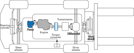
Figure 1 illustrates the baseline architecture of the lift truck that links the torque converter directly to the power shift transmission, which provides a single forwards speed and a single reverse speed, and then straight into the differential. On the other side of the engine, a fixed displacement gear pump is used to drive the steering and work circuits.
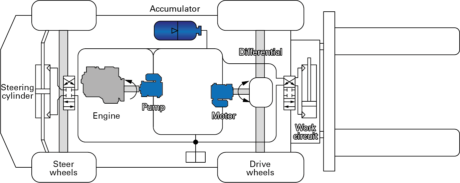
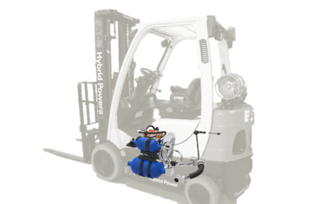
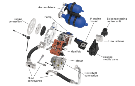
Once the baseline architecture for the lift truck was fully understood the proposed hydraulic hybrid system architecture was simulated and then designed and developed (fig.2). The new architecture, in essence, removes the torque converter and transmission and replaces them with a hybrid transmission. Similar to a hydrostatic transmission, this hybrid transmission is an open circuit with one of the ports connected to an accumulator and one connected to the tank. The pump serves multiple functions, lifting and all the work service, as well as propelling the vehicle. The addition of the accumulator and all of the controls ties the system together, making it work (fig.3).
Five elements for saving fuel
When the vehicle is idling, the engine will turn off automatically, similar to some of the high-end cars available today. When the operator provides an input to the system, signalling a return to active operation, energy stored in the accumulator is used to rotate the engine for restart. Alternatively, stored energy in the accumulator can be used to propel the vehicle or do some lifting.
By using a variable motor, variable pump and the accumulator within the hydraulic hybrid architecture, the system has lots of degrees of freedom. The control algorithm was designed to optimise the operation of the engine, which enables the engine to run as efficiently as possible under all conditions; this has made a significant impact on how fuel savings in the lift truck demonstrator over the baseline architecture are so substantial.
As the truck slows down, energy is captured in the accumulator for reuse. By eliminating the work circuit pump and delivering the precise amount of fluid required by the work cylinders, most of the metering and recirculating losses are eliminated and the work circuit becomes more efficient. In addition, this type of lift truck would require frequent brake replacements. With the hybrid lift truck, however, the frequency of brake jobs are virtually eliminated because the hybrid transmission slows down the vehicle.
The manifold is connected to the pump and routes the fluid to the motor, accumulator or work circuit. The accumulator is where all the energy is stored as compressed gas. One of the most important elements to the hydraulic hybrid architecture is the control aspect; this ties this system altogether seamlessly – controlling the speed of the engine, the displacements of the pump and the motor and the valve states.
The hydraulic hybrid system was compared to the baseline truck on a variety of different duty cycles with a diverse set of test case scenarios – some of them were lifting or not lifting, at high speed or low speed.
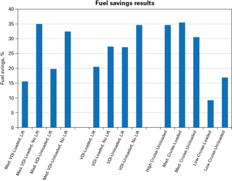
The rigorously tested proof-of-concept hybrid lift truck shows improvement in all duty cycles. All of the test case scenarios with the hydraulics hybrid system saved fuel, some up to 35% in comparison to the baseline architecture. Additional savings have also arisen in the real-world duty cycles, mainly because of the elimination of engine idle and the work circuit efficiency gains in slow and medium speed lifting.
For productivity, the hydraulic hybrid system manages engine speed and torque, yielding optimal performance. The system also reduces conventional use of brakes, which means less wear and tear on this key machine component. It also addresses the engine start, replacing the function of traditional electric starters. These innovations add up to lower maintenance costs.
With this innovation, Eaton technologists have also simplified three operator inputs into one control lever for smoother and more efficient lifting, making it an easier machine to operate. Additionally, by simplifying inputs, Eaton’s system reduces the potential for operator error.
About Eaton
Eaton is a power management company focused on providing energy-efficient solutions that help OEMs use electrical, fluid and mechanical power more reliably, efficiently, safely and sustainably. High efficiency solutions, such as the Eaton hydraulic hybrid energy recovery system are proven to be especially effective for lift truck applications. By reducing operating costs and increasing efficiency and productivity, Eaton’s hydraulic system solutions can help businesses realise a critical competitive edge.
To learn more about Eaton’s hydraulic systems, please visit: www.eaton.com/hydraulics
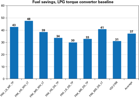
* Both graphs show fuel savings versus the baseline truck as a percentage of fuel savings. The first graph shows results from before and after testing. The second graph shows simulated savings on operational cycles that represent a variety of real-world duty cycles.


