
Federico Colombo, Luigi Lentini, Terenziano Raparelli, Vladimir Viktorov, Politecnico di Torino –
The article illustrates some of the most recent typologies of active air bearings, controlled by piezoelectric actuators. This active control methodology is used to obtain much higher performances than with conventional air supports.
Air bearings find their main use ambit in all those applications needing high precisions, like for instance micro-machining performed by machine tools (micro-drilling, micro-milling and so on), measuring machines, calibration machines, medical instruments and so on.
The great precision of these systems springs from the absence of contact between the surfaces in relative motion. That separation is obtained by interposing a subtle air meatus between the mobile part and the fixed part. The main advantages deriving from such absence of direct contact are the following: the almost total absence of friction, of wear, the absence of hysteresis, of stick-slip and the low heat generations. Besides, the air lubrication, unlike other types of lubrication currently used, does not contribute in any way in the environmental contamination of workstations.
Even if the performances of the current air systems are already convincing, the modern market urges manufacturers and designers to obtain new increasingly performing and cutting-edge technologies, sometimes imposing also very strict specifications on sizes and costs. For this reason, and thanks to the recent drastic reduction of costs of the new control, actuation and monitoring (actuators, sensors etc.) technologies, we are more and more oriented to integrate the “old” typologies of air bearings with “smart” actuators and systems (1), (2) like for instance the nowadays widely used piezoelectric actuators (3).
This article illustrates some of the most recent typologies of active-type pneumostatic bearings (4) which exploit in their inside sensors, controllers and especially piezoelectric actuators in order to achieve systems characterized by high performances in static and dynamic field.
In particular, we will describe in the order: two prototypes of active flat pneumostatic bearing, the first devised and implemented by the Department of Mechanical and Aerospace Engineering (DIMEAS) of Politecnico di Torino (5), the second by the Department of Mechanical Engineering of KU, in Leuven (Belgium) (6), (7), (8), (9) and a hybrid aerostatic rotary bearing for the support of high-speed rotors that has been implemented by the Department of Mechanical Engineering of DTU, in Lyngby (Denmark) (10), (11).
DIMEAS prototype by Politecnico di Torino
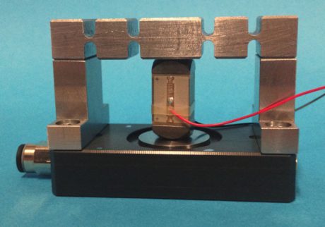
The prototype of active pneumostatic bearing under examination was implemented by the Department of Mechanical and Aerospace Engineering (DIMEAS) of Turin Polytechnics (5) and it is shown in the opening picture.
This component was manufactured starting from a conventional bearing model, currently available on the market, of the HPR series produced by Mager®, which was successively integrated with a piezoelectric actuator (PI P-888.31 PICMA Multilayer Piezo-actuator), a kinematic motion and an industrial controller of PI type.

The conventional bearing features a rectangular basis with sizes of 60 and 30 mm respectively. The “active” surface of the bearing has two feeding holes of about 0.25 mm of diameter and two “C” spiral channels, both symmetrically positioned as to the minor axis of the base of the bearing itself.
To allow the integration with the piezoelectric actuator and with the kinematic motion, the physical structure of the bearing was opportunely modified by inserting a plate provided with a hemispheric seat to permit a correct contact between bearing and actuator and with two small lateral columns, equipped with seats for dowel pins and threaded holes.
The kinematic motion consists in the alternate interposition of virtual hinges, commonly indicated in technical literature as “flexure hinges” (12) and with small beams with rectangular section. Virtual hinges are sudden section narrowing introduced inside mechanical structures in order to operate as hinge-type internal disconnections. In fact, combining virtual hinges and beam-type elements it is possible to obtain real kinematic motions to perform micro-positioning and regulations. This is made possible by exploiting the minor stiffness of the zones with smaller section.
It is worth underlining that the sizes of virtual hinges must be opportunely designed from both a static and a dynamic point of view. It is necessary to verify that under nominal operation conditions they are subjected to stresses well under the elastic limit of the material, in order to avoid the phenomena of work hardening and hysteresis associated to the operation in plastic field. Nowadays, virtual hinges find their main application field in MEMS (Micro Electro-Mechanical Systems) systems and in literature it is possible to find a broad documentation about the matter (13), (14), (15).
In the case of the pneumostatic bearing prototype developed, the virtual-hinge kinematic motion has been introduced both to favour the action of the piezo actuator, permitting to reduce the actuation force value with unchanged actuator stroke and to guide the piezo deformation, in such a way as to allow only vertical translations to its central beam.
The figure 1 describes the operation principle of the implemented system. Under nominal conditions, the system runs as a standard pneumostatic bearing (according to the characteristic curves of load, consumption and stiffness), working in presence of an air meatus height h, of a working height H (given by the sum of the vertical size of the Z bearing and the height of the h layer) and supporting a F load (work condition indicated in figure 1 at n° 1). Obviously, all the values of the parameters above mentioned are function of the pressure with which the system is fed.
In presence of force variations (operating condition indicated in figure 1 at n° 2), indicated with dF, owing to the compressibility of the air meatus, we will have consequent dh variations of the same and therefore also variations of the working height dH. In particular, in the case represented in figure 1, we consider an increment of the dF load with regard to its nominal value, which therefore will lead to a reduction of the meatus height equal to dh and then also to the same reduction of the height (dh=dH under the hypothesis of stiff bearing).
When the control system is operating, these variations are detected by position sensors (or alternatively through other indirect-type measurements) and analysed by the PI controller that will compensate them, providing an opportune control signal to the actuator.
Following the compensation action, the system is then brought again to its initial working position, thus attaining a system of infinite static stiffness[1]..
![Fig. 3 – Active pad controlled by 3 piezoelectric actuators implemented by the Department of Mechanical Engineering of KU in Leuven [abstract from (9)].](https://www.powertransmissionworld.com/files/2017/01/Figura-3-460x188.jpg)
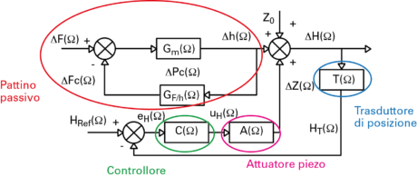
Figure 2 shows the block diagram of the control system integrated inside the bearing, where Gm(Ω), GF/h(Ω), C(Ω), A(Ω) and T(Ω) respectively represent the transfer functions of the mass supported by the bearing (inertia contribution), of the air meatus (dampening contribution and stiffness), of the controller, of the piezoelectric actuator and of the position transducer. As highlighted in the figure, the passive bearing, according to the operation conditions (feed pressure, F supported load), will grant a certain K stiffness and a certain value of the controlled H height (given by the sum of the h air meatus and the vertical Z0 size of the bearing). The value of the controlled HT height, measured by the T position transducer, is then “sent” to the controller that compares it with the desired HRef reference value. This comparison allows calculating the eH position error that will be consequently annulled by the action of the piezoelectric actuator A (through the uH control signal).
Prototype by KU Leuven
![Fig.4 – Operation principle of the active Bearing controlled by hv taper variation [abstract from (8)].](https://www.powertransmissionworld.com/files/2017/01/OP_2016_002_LENTINI4-460x440.png)
Figure 4 shows a scheme of the active surface of the bearing from which we deduce how this features a geometry of convergent conical type, whose variations depend on the variation of the hv dimension. The technical literature shows how surfaces of this kind allow having more stable systems, less sensitive to the surface irregularities and, sometimes, able to grant infinite or even negative (16) static stiffness.
The active surface (inferior) of the bearing is constituted by a thin circular plate that is centrally fixed to a central column connecting it with the upper part of the bearing. The circular plate is supported and handled by three piezoelectric actuators positioned symmetrically along its circumference.
In presence of nominal operational conditions, the bearing works as a standard bearing with convergent surface. On the contrary, in presence of variations of the supported load, thanks to the presence of a closed-loop control system, the integrated control system reacts by controlling the voltage to the terminals of the three piezo actuators, in such a way as to deform the circular plate and to vary the taper of the meatus and, consequently, the pressure distribution in its inside. The value of output voltage from the controller is calculated according to a concentrated-parameter mathematical model of the entire system described until now and able to restore the original meatus height without altering the value of the bearing feed pressure.
The scheme in figure 5 summarizes the operation of the above described control system through a block diagram representation resembling the one shown in figure 2. Here the system is subdivided into a passive part, reported on the right of the diagram (mechanical system and bearing passive stiffness) and associated to the bearing operation without automatic regulation actions, and into an active part, composed by the controller, its amplifier (controller + amplifier) and piezoelectric actuators (actuator). The active part of the system assumes a central role since on it depends the accuracy and the rapidity (bearing response) with which the positioning systems manages to restore the wished working height.
The available experimental results (8) show that an active pneumostatic bearing of this kind succeeds in achieving an infinite static stiffness and in reaching passbands even in the order of 300 Hz.
DTU Lyngby prototype
The active bearing described is a hybrid bearing of rotary type used for the support of high-speed rotors implemented by DTU in Lyngby (Denmark) (10), (11). This system consists of a rotary aerodynamic bearing that has been integrated with magnetic-type actuators, to improve their scarce starting performances that are typical of this kind of bearings, and with four piezoelectric actuators inserted circumferentially into the bush in order to compensate for the dynamic unbalances of the rotor during its steady-state operation.
![Fig. 5 – Block diagram of the closed-loop system used for the control of the active bearing engineered by KU in Leuven [abstract from (8)].](https://www.powertransmissionworld.com/files/2017/01/OP_2016_002_LENTINI5-460x309.png)
![Fig. 6 – Detail of one of the injection channels [abstract from (11)].](https://www.powertransmissionworld.com/files/2017/01/OP_2016_002_LENTINI6-150x150.png)
The position of the rotating shaft is monitored by position sensors that measure the eccentricity components along the X and Y direction.
The control system is obtained on the basis of a concentrated-parameter mathematical model of the bush-rotor system that allows improving the system performances in terms of dynamic unbalance.
Conclusions
The article shows three examples of active pneumostatic bearings, where it is possible to obtain almost infinite stiffness thanks to the closed loop control. The first prototype (Turin Polytechnics) uses a PZT actuator and a position sensor; the control directly operates on the vertical dimension of the bearing in order to keep the value constant following to load variations. The second prototype uses three piezo actuators and a central position sensor; the regulation occurs by deforming the bearing in order to modify its loading capacity. The third prototype exploits four PZT actuators and two displacement sensors; the control operates in such a way as to reduce the shaft runout inside bearings and to improve their stability. The three solutions have higher costs than standard passive pneumostatic bearings but they allow attaining much higher positioning precisions and they are therefore suitable for high added-value applications.
[1] The static stiffness is defined as
[2] Piezo actuators are actuators with high dynamics and high density of actuation energy per volume unit (2).


