
8 best ways to wreck your coupling driven system (and how to avoid them in the future).
Keeping a servo driven system running at peak efficiency is no simple feat. Misunderstanding performance criteria such as misalignment, torque, or RPM can be all it takes to cause a critical and costly failure. The following are the 8 best ways to consistently sabotage or damage your coupling driven system (and how to avoid them in the future).
1. Choosing the wrong coupling
Unsurprisingly, one of the most effective and common ways to wreck your system is by selecting the wrong coupling. There are many factors a design engineer must keep in mind to avoid coupling failure. Balancing criteria such as torque, RPM, shaft size, tolerances, operating environment, and misalignment is paramount to selecting the right coupling.
2. Not identifying misalignment
Most servo applications have one or more forms of misalignment. This is a primary concern, since misalignment can cause stress to system components such as bearings, not just to the coupling itself. Misalignment is often caused by a tolerance mismatch from the driving side of a system to the driven side.
This can be caused by a variety of factors, including parts from different manufacturers, inaccuracies in assembly, system/motor movement during operation, system component wear, poor mounts, and thermal shaft expansion. Each coupling style can accommodate different amounts of misalignment.
Designers must understand the nature of existing misalignment to determine if a high misalignment coupling is needed at the expense of factors such as torque, or if corrective system adjustments are necessary before selecting a coupling.
3. Exceeding RPM recommendation
System requirements determine speed and in precision driven servo systems it is possible to have speeds of 2,000, 5,000, 10,000 or even 25,000 RPMs. Unfortunately, not every coupling can handle higher speeds, even if they are otherwise a perfect fit for the system. Exceeding the manufacturer’s RPM rating can cause coupling failure or damage to system components. Even if the coupling is rated for high RPMs, greater speeds increase the effects of misalignment. For example, a disc coupling might accommodate very slight angular misalignment at its maximum rated speed of 10,000 RPM without adverse effects on the coupling or system components but will cause damage at a speed of 15,000 RPM with the same misalignment. Designers must know the maximum operating speed the coupling will experience to select the right one. It is also important to understand how manufacturers determine ratings – with performance factors in isolation or everything at max.

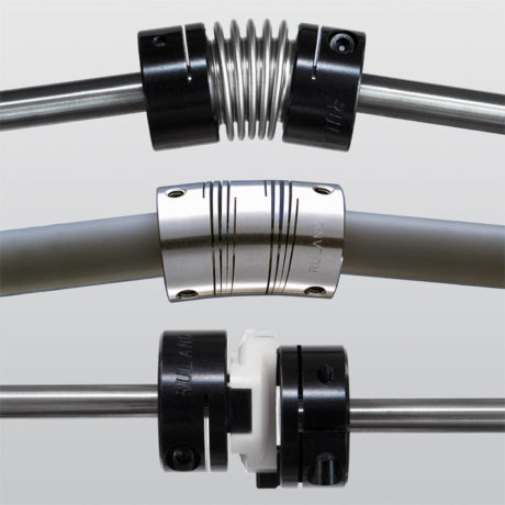
4. Not considering coupling wear
Couplings are designed to be the wear element in most systems to protect more expensive components such as bearings and motors. Each coupling wears differently and will fail in a different way. Beam and bellows couplings will completely fail stopping power transmission when they reach the end of their service life. Disc, jaw, and oldham couplings will lose zero-backlash, but still transmit motion. Depending on the application requirements one of these wear types may not be desirable. Additionally, designers must consider if the coupling requires maintenance or replacement when reaching the end of its service life. Beam, bellows, and disc couplings are maintenance free and require complete replacement after a failure whereas oldham and jaw coupling performance can be restored by replacing the insert after failure. During the testing phase, designers can better understand the service life of the coupling and give a recommended PM schedule to best avoid unplanned downtime.
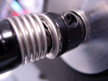
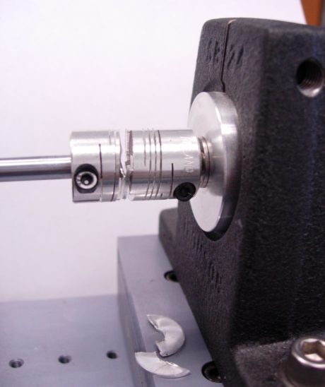
5. Installing the coupling incorrectly
There is no faster way to undo the work of selecting the perfect coupling and optimizing system parameters than installing it incorrectly. For example, uneven torqueing of the screws, incorrect shaft penetration, installing off-center and compressing or stretching the coupling can lead to a failure or premature wear of sensitive system components.
The safest option is to follow the manufacturer installation instructions, especially when accompanied by videos.
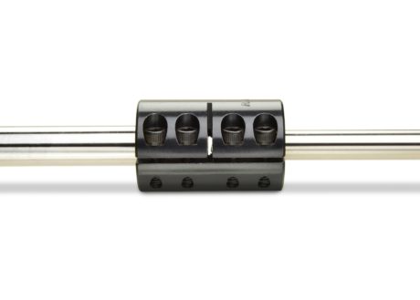
6. Buying Generic Couplings
Not all couplings are created equal, or for the same purposes. Some couplings are manufactured with common specifications, tolerances, and designs, such that they are nearly indistinguishable from many others on the market. This may be suitable for systems with limited performance requirements, but precision systems often require or benefit from couplings with additional capabilities.
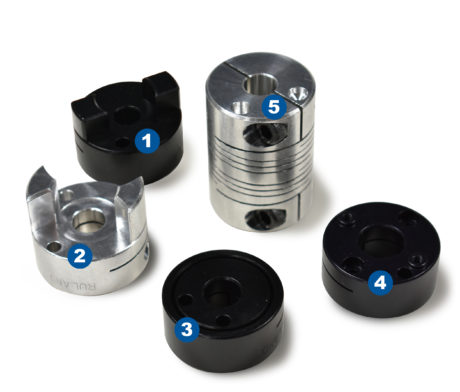
For example, balanced designs are not the industry standard for most couplings. In an application like printing the reduced vibration afforded by a balanced design is a necessity – less precise couplings would cause banding and expensive waste or downtime. The five servo couplings in the picture above all have balanced holes for a balanced design. 1: oldham coupling 2: jaw coupling 3: bellows coupling 4: disc coupling 5: beam coupling.
7. Selecting the Coupling Late in the Design Process
Far too often motion control couplings are selected late in the design process. This can limit which coupling is used in the system and the performance it delivers. For example, a system requiring high torque and speed may need to use a disc coupling but ultimately have an envelope that is too small to fit a double disc type, forcing the designer to select a single disc type. While it may meet the speed and torque requirements, single disc couplings cannot accommodate parallel misalignment, meaning that the system will require greater precision during installation to eliminate the chance of parallel misalignment, likely adding cost and complication.
Considering the coupling earlier in the design process would have likely eliminated this issue, saving time and money. To make the design process easier, manufacturers may have CAD, detailed product information, and technical support available on their website.
8. Failing to Test
One of the first rules of system design is always test. While everything may look correct in the design, it is hard to determine suitability until the coupling is run under common use conditions. Extensive testing prior to use in live systems can help maximize coupling and system performance. Manufacturers can assist in the design process with technical support and by providing product samples to ensure proper coupling selection.
About Ruland
Ruland Manufacturing Co., Inc. is a privately owned company founded in 1937. We have carefully and responsibly manufactured high performing shaft collars, rigid couplings, and motion control couplings for the past 40 years and begun distributing machine components from carefully selected suppliers.
SEE ALSO THE INSTRUCTIONAL VIDEO SERIES: https://youtu.be/GNPmjaejq-g


.)