
– Gianni Niccolini, Politecnico di Torino
We are illustrating here the friction-related issues in the motion of pneumatic cylinders. From the microscopic friction description in general to the discussion of the phenomenon in pneumatic cylinders in presence of lubricant. With an (apparent) surprise: the use of not excessively polished surfaces is advantageous for smoothness.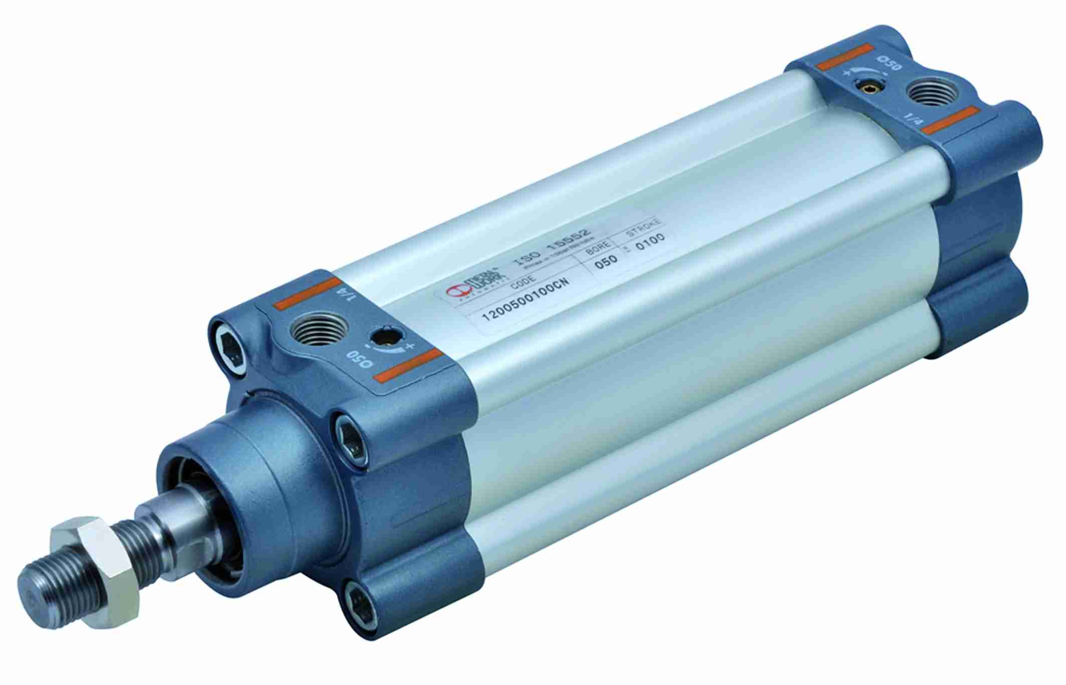
Microscopic friction mechanism
Friction is a force exerted between two bodies placed in contact and, in general, it opposes their reciprocal motion. In our daily life, we cannot avoid friction forces. In a car, about 20% of the fuel is used to contrast the frictional resistance in the transmission engine. On the other hand, if friction was completely absent, we could not walk or cycle. We could not hold a pencil in our hands or, if we managed it, we could not write. Nails and screws would be useless, we would see all fabrics disintegrate and all nodes dissolve.
To explain the existence of the friction force, it is necessary to examine the fine structure of the contact surfaces of the two bodies sliding each other. Even a perfectly polished metal surface is far from being defined flat on a microscopic scale. When two surfaces are placed one against the other, only their most protruding points get in touch (we should imagine the French Alps turned upside down and laying on the Italian Alps). The effective microscopic contact area s is much smaller than the apparent macroscopic contact area S, by a factor that can reach even 104.
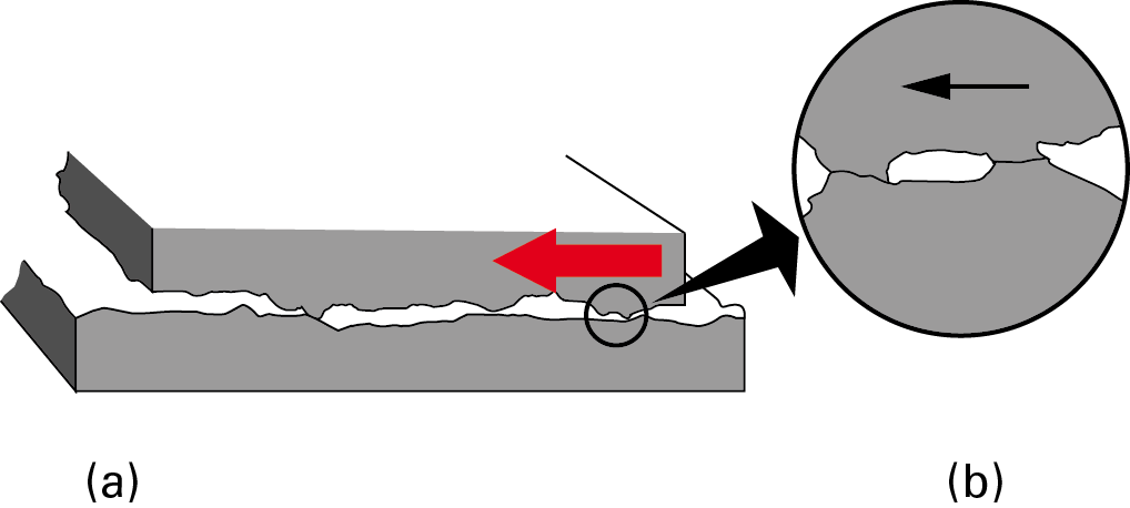
Let us consider two A and B bodies, the first of which presses on the second with its weight Fp, which therefore transmits on the small s area a very big pressure P = Fp /s. Such load, on each effective contact zone, can produce local plastic deformations that favour some cold solders among the asperities in contact and therefore generate among them some structural “bridges”. This mechanism is shown in figure 1.
To set the A body in motion, a force applied to it must in fact be able to break the bridges generated by the cold soldering, whose overall resistance is summarized by the (maximum) value of the static friction force. When the body is already in motion, the opportunities of generating stable bridges are minor and therefore the latter give birth to a lower dynamic friction force than the static friction one. Since they are two surfaces that slide one against the other, the friction is called sliding [1].

Friction in pneumatic actuators
While in some cases friction is providential, or even indispensable, on the contrary in the motion of machinery parts in contact one another the presence of friction is certainly noxious. Both because friction is a passive force that opposes the motive power and then source of energy dissipation (through transformation of mechanical energy into heat), and because it produces wear of the sliding parts, shortening the machinery life. We can obtain a drastic friction reduction by making use of lubricants. It is the case of pneumatic actuators, members able to create motion along a straight line (in contrast with the rotary motion of a standard electric motor) using compressed air as energy vector [2, 3].
A pneumatic actuator is typically constituted by a hollow cylinder where slides a piston anchored to a rod with sealing gaskets. The piston performs a rectilinear motion with its rod from the position of retracted rod to the position of extended rod and vice versa. The motion in the two directions is operated by sending compressed air alternately to the front chamber or to the rear chamber of the cylinder.
Actuators, or pneumatic cylinders, perform a mechanical work by exerting an adequate force in the application point.
The force is given by:
Force = Pressure × piston area
(in the return direction, it will be necessary to deduct from the nominal piston area the one physically taken up by the rod).
The force obtained by multiplying area and pressure is a theoretical force because, in the calculation of the force developed by the piston, we will deduct what we need to win the friction and to move the weight constituted by rod and piston. Friction losses are due to the sliding of the sealing gaskets of the piston on the cylindrical chamber walls [6,7].
To facilitate the piston sliding, meanwhile avoiding that gaskets undergo a fast wear, it is opportune to interpose a lubricant layer among the surfaces of the piston gaskets and the cylindrical chamber, to prevent them from sliding directly one against the other. In this case, the resistance to motion is opposed by the fluid “layers” that slide one on the other (it is as if the moving bodies “floated”, supported by a liquid). This type of friction, called viscous, is always much lower than the sliding friction caused by the direct contact between two dry surfaces.
The friction of a gasket depends on the piston feed speed and on the operating pressure. In presence of lubricant, we can identify three friction conditions, according to as many lubrication states, which identify the Stribeck curve, as shown in figure 3 [4].
When the piston is stationary for a certain time in one of its two extreme positions, the lubrication conditions stop, since the compression exerted by the gaskets against the inner cylinder wall extinguishes the lubricant film. Therefore, at the pickup the piston must win a static friction, defined also as adhesion, due to the “dry” contact with the cylinder (sliding friction condition).
As soon as the piston moves, however, the lubricant film is restored and the friction suddenly diminishes, reaching its minimum value (partial lubrication state). The sudden friction reduction generates the annoying “stick slip” phenomenon and the consequent inching of piston, which exerts destabilizing effects on the position and speed control.
Once overcome the speed that leads to the full lubrication regime, the two surfaces are completely separate and are restored the conditions of normal hydrodynamics where friction increases with speed (regime of viscous friction) [5].
In presence of lubricant, too, the friction is influenced by the elastic properties of materials (hardness and elasticity of gaskets) and by the state of surfaces (sizes and finish of the gasket supporting surfaces, roughness of the cylindrical chamber). Concerning gaskets, they undergo elastic deformations that cause resistance as to the motion, generating efficiency losses. It is worth underlining that the gasket shape can influence their service life, and then reduce friction effects. The presence of rounded edges, in fact, allows preserving the lubricant film longer and better holding the grease inserted between the two gaskets of a piston [8-10]. Shape effects therefore permit a further operation improvement, with initial greasing without lubrication.
![Fig. 3 – Stribeck curve: trend of the friction force of a gasket according to the piston speed (on the abscissa the speed and on the ordinate the friction). 1) sliding friction; 2) partial lubrication; 3) viscous friction [4].](https://www.powertransmissionworld.com/files/2015/09/OP_2014_001_NICOLINI3.png)
Roughness, meant as the whole of the deviations of the real surface compared to the technical surface, relates to the unavoidable (as we have seen) geometric micro-imperfections under the form of grooves or scratches, which are measured by profilometers and expressed in microns (mm). It is defined by a series of parameters indicated in figure 4a. The first is the surface roughness Ra, defined as the arithmetic mean of the absolute values of the real profile deviations as to the centre line of such profile; that measurement refers to a base length l of the analysed profile, chosen to avoid the influence of other types of irregularities linked with specific imperfections of the manufacturing process. The second parameter is the total roughness Rt, which is the distance between the highest crest and the deepest groove included in the measurement trait.
![Fig. 4 – Rough profiles: (a) characteristic roughness parameters; (b) profile with plastic deformation machining; (c) profile with stock removal machining [9]; (d) qualitative trend of the dry friction coefficient with roughness.](https://www.powertransmissionworld.com/files/2015/09/OP_2014_001_NICOLINI4.png)
Appropriate roughness values for the sliding surfaces are included between 0.2 and 1 mm, where minor values are necessary when we use gaskets not lubricated. We can easily guess that an excessively rough surface with sharp edges (roughness > 1.5 mm) rapidly wears gaskets. On the other hand, an excessive finish of barrels reduces the service life of gaskets, since a too smooth surface is devoid of lubricant pockets and therefore leads to a fast wear. The ideal solution is therefore represented by a surface without superficial crests, equipped with scarcely deep grooves acting as lubrication pockets.
In case of dry friction, the qualitative trend of the friction coefficient is reported in figure 4(d). We can see that low and high roughness, for the current engineering materials, cause high friction coefficients compared to average roughness ones.
The research in this engineering ambit is extended to the exploration of innovative materials. Recently, Airpel® has implemented a pneumatic cylinder with a special coupling “graphite piston/Pirex glass cylinder”, with the double advantage of drastically reducing frictions and of not needing gaskets (while keeping the air leakage at negligible levels).
Thanks
The author thanks the Italian companies Metal Work at Concesio (Brescia) and Pneumax in Lurano (Bergamo) for the information and the images kindly provided.
Bibliography
[1] D. Halliday, R. Resnick, J. Walker, Fondamenti di Fisica, Casa Editrice Ambrosiana, 2005.
[2] V. Cuffaro, A. Mura, A. Manuello Bertetto, R. Pinna, Boccole di guida di cilindri: la misura della pressione di contatto con carte sensibili, Oleodinamica Pneumatica, pp. 60-65, (gennaio 2011), ISSN 1122-5017.
[3] A. Manuello Bertetto, L. Mazza, Attuatori pneumatici a basso attrito, Oleodinamica Pneumatica, pp. 54-59, (gennaio 2011), ISSN 1122-5017.
[4] http://it.wikipedia.org/wiki/Lubrificante.
[5] Schroeder, L.E., Singh, R., Experimental Study of Friction in a Pneumatic Actuator at Constant Velocity, J. of Dynamic Systems Measurement and Control (ASME), 115 (3), 1993, p.575-577.
[6] Eschmann, R., Misura dell’attrito di guarnizioni di cilindri pneumatici., Fluid, 25 (8), 1992.
[7] Raparelli, T., Manuello, A., Mazza, L.: Experimental and Numerical Study of Friction in an Elastomeric Seal for Pneumatic Cylinders. In: Tribology International, 30 (7), 1997, p. 547-552.
[8] G. Belforte, M. Conte, A. Manuello, L. Mazza (2011), Performance and Behaviour of Seals for Pneumatic Spool Valves, Tribology Transactions, vol. 54, pp. 237-246. – ISSN 1040-2004.
[9] G. Belforte, Manuale di Pneumatica, Milano, Tecniche Nuove, 2005.
[10] G. Belforte, A. Manuello Bertetto, L. Mazza, (2013), Test rig for friction force measurements in pneumatic components and seals, Proc. of IMECHE Part J, Journal of Engineering Tribology, ISSN: 1350-6501, DOI: 10.1177/1350650112453522.


