
In this article, we are describing the friction phenomena in pneumatic components, discussing some modelling aspects and some energy and manufacturing implications.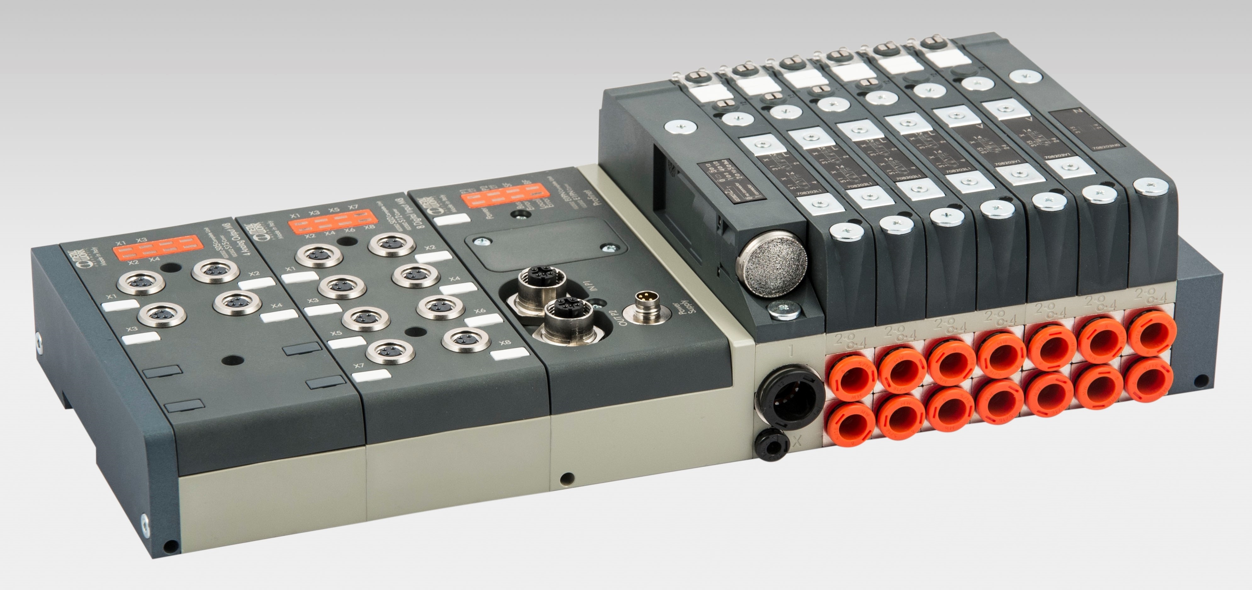
The friction phenomenon arises also in pneumatics, which performs motions, regulations, automations and drives of machines. The friction force acts by contrasting the relative motion of bodies in contact. If it emerges between still surfaces, it is called static friction whereas between surfaces in relative motion it is defined dynamic friction. Friction, in presence of sliding, dissipates energy that, in its almost totality, is converted into heat; only a tiny portion is transformed and stored as plastic deformation energy. The temperature in contact zones increases hand in hand with the rise of the friction and of the relative speed whereas it decreases with the growth of the thermal conductivity and of the specific heat of the materials in contact. The temperature can rise to such levels as to weaken and, in extreme cases, melt the contact zones, causing micro-structural modifications.
That force has been observed since Aristotle’s age, but Coulomb (1736-1806), recovering other scholars’ studies, analysed thoroughly the sliding and rolling friction [1]. Coulomb immediately made a distinction between static friction and dynamic friction, studying them separately. He identified four phenomena that rule the static friction: the nature of the materials in contact, the area of the surfaces, the load that surfaces bear and the duration of the contact. Besides, he studied the dependence of the dynamic friction on the three previous causes and, in addition, on speed. Currently, the friction phenomenon has assumed a wider connotation with the development of tribology, science that studies the interactions between surfaces in relative motion, the adhesion, the lubrication and the wear.
The new technological instruments, which allow executing accurate measurements at a micro and nanometric magnitude scale in well-defined contact geometries, and up-to-date computers permit the experimental research to focus on the friction characteristics on a nanometric scale level. Nano-tribology is at stake with the target of defining the particular friction properties at nanometric level and of trying to understand the phenomena of the macroscopic friction at atomic level. A direct explanation of the macroscopic friction in terms of atomic interactions can be hardly defined and, on the other hand, as per [2], the most important friction mechanisms originate not at atomic scale level but at a mesoscopic level. Concerning this, it is worth noticing a comparison with chemistry, which cannot be completely defined according to a standard model of Physics, likewise the friction cannot be completely explained on the basis of the physical mechanisms at atomic level [2].
The research is constantly developing and the friction phenomenon in pneumatics is studied with notable interest to try to find solutions that allow reducing it wherever possible or using it to our own benefit.
Friction in compressed air systems
The compressed air is used as energy vector since it brings notable advantages, even against a noteworthy cost for its operation. Air is present in nature in almost unlimited quantity, however, to be used as energy vector, it must first filtered, then compressed at higher pressures than the atmospheric one, finely filtered again and finally cooled and treated before being input into the ducts and destined to final utilities [3]. The compressed air plays a relevant role in industrial sectors, for instance in handling systems with pneumatic transport, or in lifting systems with air bearings and in the processes of regulation and control of pneumatic automation; besides, it is present in all tools of pneumatic type, such as drills and screwdrivers.
A compressed air system is commonly composed by five macro-elements: the compression machine, the tank, the air treatment system consisting of dryer and filters, the net and utilities.
In the compressor, optimization principles lead to a reduction of dissipations due to mechanical friction. It is possible to classify compressors according to their characteristics. They are subdivided into two big categories: volumetric compressors and dynamic compressors. The most used in the industrial sectors are volumetric compressors, rotary screw ones, which in their turn are split into other two categories: lubricated screw compressors where the oil lubricates the screw group and “oil free” screw compressors, where the oil is used only for the cooling of the screw group [3]. The presence of mechanical organs in contact and in relative motion – let us think of the piston-cylinder coupling in alternating volumetric compressors – requires the implementation of a lubrication system for the reduction of frictions and wear. We must however avoid the mixing between lubricating oil and compressed air, both to avoid the oil pollution by the air and to achieve the total absence of impurities in the air sent to the utility.
In filters and dryers, which have the function of eliminating eventual solid particles from the compressed air, degraded oil vapours and the condensate wetness, strong phenomena of fluid-dynamic friction occur, as it happens in tower filters with adsorbent carbon, where take place phenomena of airflow channeling and carbon displacements, with wear-out of the same. This leads to an accumulation of particulate and consequent filter obstruction, with increase of fluid-dynamic friction phenomena. To avoid losses caused by fluid-dynamic friction, they have implemented smaller and lighter filters, however equivalent to tower filters with the same flow rate, with active carbon cartridges that allow a fast maintenance and a more efficient use of the active carbon bed, thus avoiding high friction, creation of dusts and filter obstruction.
In the distribution net, losses are due to the friction between the fluid and the pipe walls depending on the speed of the fluid itself; for this reason, it is preferable to keep the fluid speed under 20 m/s. The losses distributed in rectilinear ducts with circular section depend on the friction factor, on the fluid density, on the duct length, on the fluid speed and on the duct diameter. The friction factor is perhaps the most important parameter concerning the possibility of reducing the pressure drop as, if the system distances are more or less defined by process requirements, the factors that determine the friction are linked with the material typology composing the net and with the fluid speed; therefore they feature more intervention margins [3]. If we diminish the friction factor, distribution costs decrease.

Friction in valves and cylinders
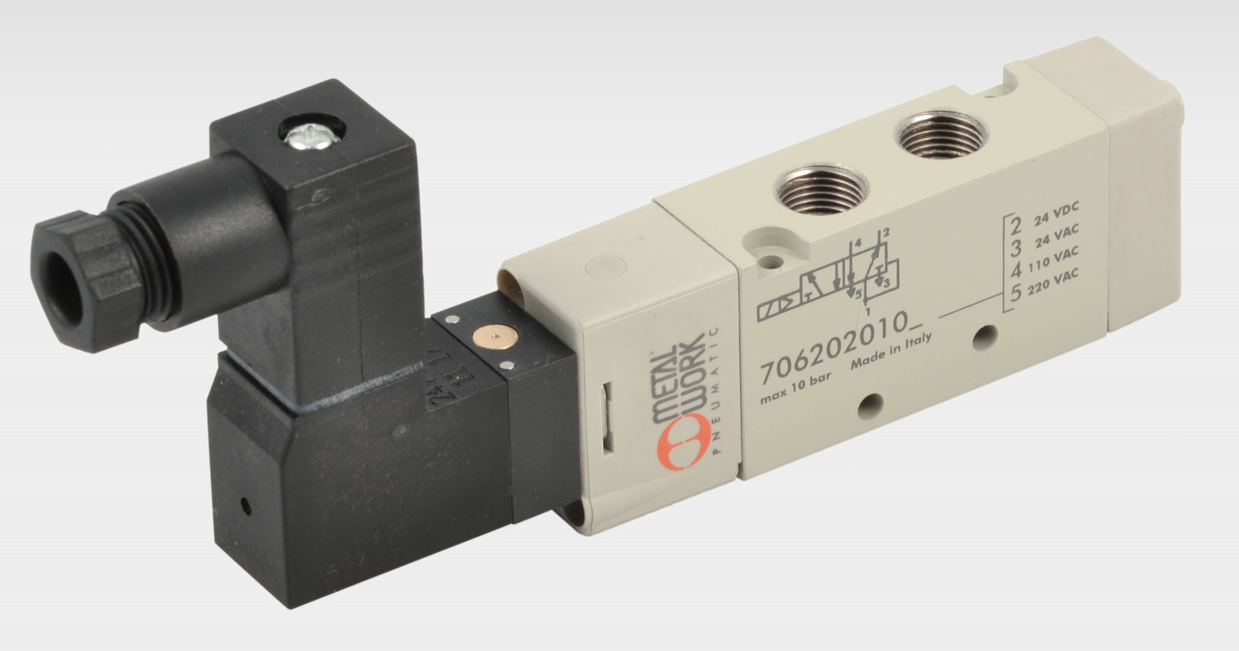
Friction plays a fundamental role in pneumatic valves. Their function is defined by the type of connection they allow implementing and by the proposed variants. The connection type depends on the number of ways and on the internal scheme whereas the variants correspond to the number of positions of distributing organs. In the figure 1, we can see a S70 Mach 16 solenoid valve, the same figure shows the section of the same solenoid valve that highlights the technical solutions adopted to preserve the tightness and to contain friction.
Actuators, where friction phenomena are particularly significant, deserve particular attention. Actuators represent the final equipment of the automatic system, where the pneumatic energy is converted into mechanical work. Pneumatic actuators can be classified in three types: linear actuators or cylinders, with limited rotary motion, or rotary cylinders with continuous rotary motion or continuous rotary pneumatic motors. In linear cylinders, when the piston is stationary in a position for a certain time, the compression of the seals against the inner wall of the liner determines the lubricant ejection. In this position, no lubrication occurs and the piston, at the pickup, must overcome friction forces on a surface badly lubricated. At the pickup, the static friction is higher that the dynamic friction and the “stick slip” phenomenon can occur, i.e. that mechanical phenomenon that regards the sliding friction characterized by violent accelerations that occur between two surfaces in sliding contact. Immediately after, the piston recovers the correct lubrication state.
Pneumatic component manufacturers have found technical solutions to shift from standard friction conditions to low friction conditions, minimizing energy dissipations.
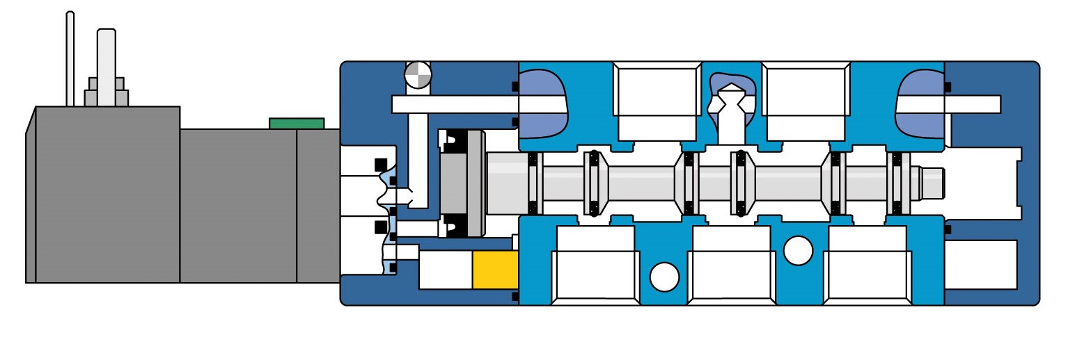
In the figure 2, we can observe the section of an ISO 15552 pneumatic cylinder that, in the standard version, is equipped with two lip seals for the piston and a double-lip seal for the rod.
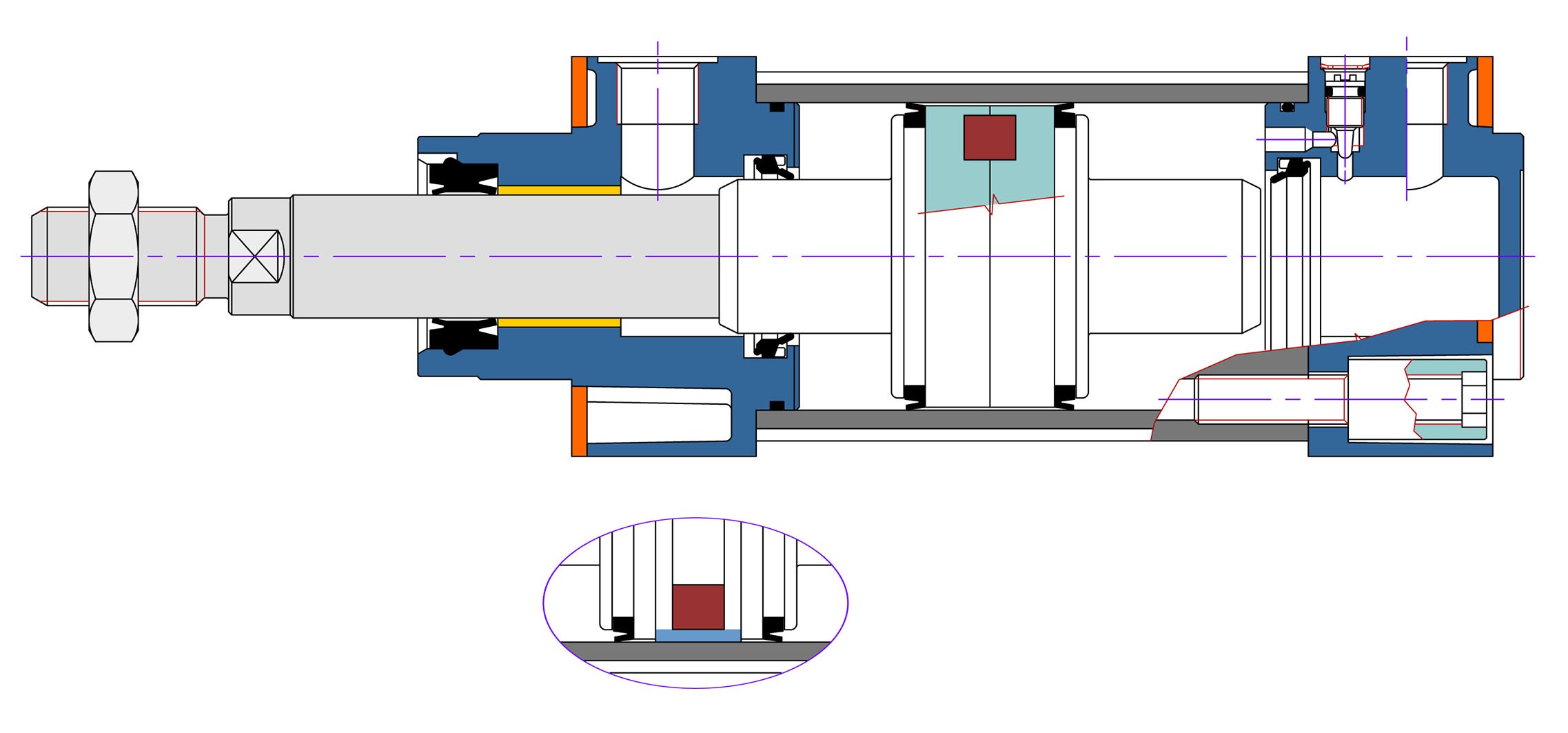
In figure 3, we can observe the section of an ISO 15552 BA very low-friction pneumatic cylinder with a single seal with “floating” assembly for the piston and a small-size single-lip seal for the rod. Actually, the low-friction version provides for a series of devices: special grease, piston with calibrated external diameter, more precise machining to grant the perpendicularity and the concentricity between surfaces.
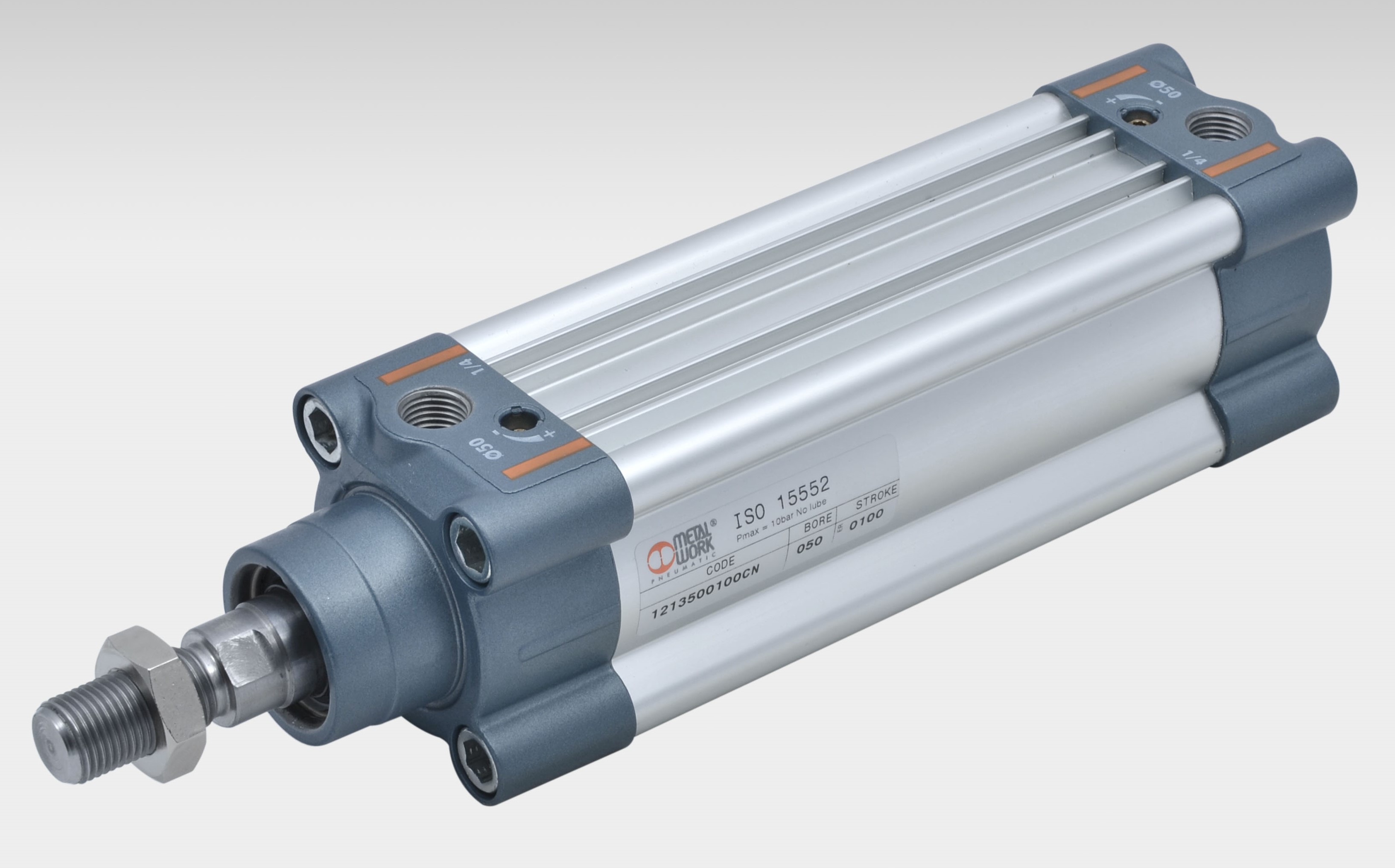
Fig. 3 – Section of ISO 15552 BA very low friction pneumatic cylinder (Credit: Metal Work Spa (Brescia, Italy) [14].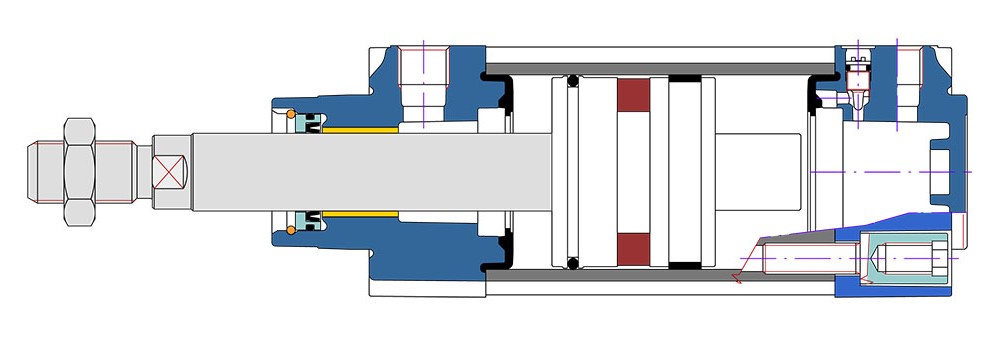
The effects of the friction between contact surfaces, at the seals of the actuators, create difficulties in the control precision. Most of non-linear phenomena, in a pneumatic position servo-system, are ascribable to friction forces. Their presence makes the position control difficult, because it can cause stationary positioning errors and errors in the tracing of a trajectory. In addition, under determinate situations, stick-slip motions can occur.
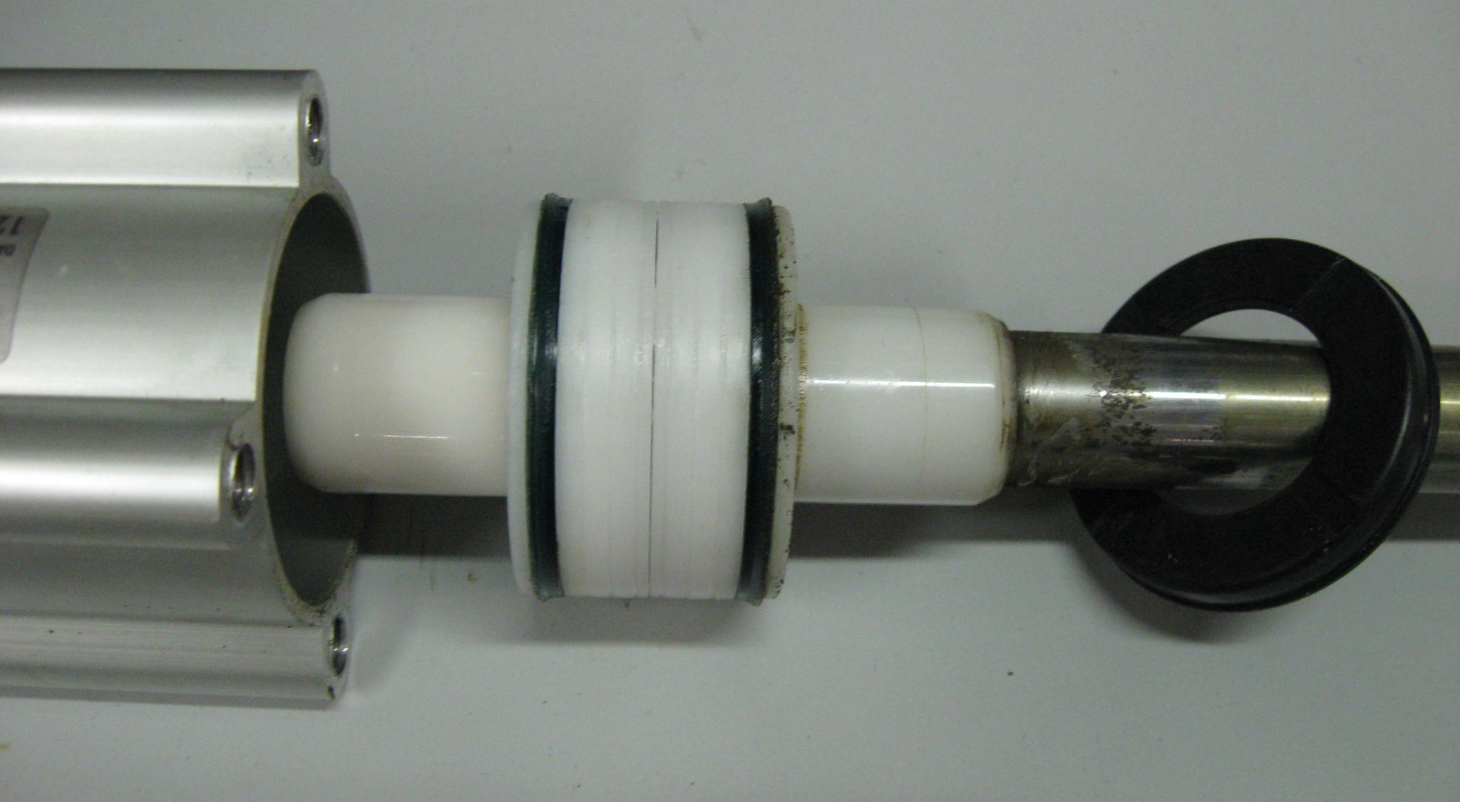
In figure 4, we can see a mobile group of cylinder subjected to prolonged work cycles, where friction phenomena are highlighted by the wear of parts in contact in relative motion.
In the dry friction between flat surfaces, it is possible to model the phenomenon as a whole of forces of elastic and plastic deformation of microscopic asperities in contact [4]. There are friction models that in literature are subdivided into static and dynamic. Among static models, classic ones are based on different components, each of them takes care of some aspects of the friction force. The static friction force appears at null relative speed and opposes to the sliding motion with a tangential force to the module contact that is, as maximum, equal to the static friction force.
Concerning the static friction, an interesting model has been proposed by Karnopp [5]. This model has been defined in such a way as to represent the static friction phenomenon at null relative speed between surfaces in contact and to avoid the alternation of models for stick-slip motion. Among dynamic models, it is worth mentioning the model developed by Dahl [6-8], able to represent the position control in systems with friction. That model has been used for the representation of the motion of servo-systems in presence of friction [9, 10]. We can notice how in Bliman and Sorine models, they define the relative speed of the friction force module [11-13].
Conclusions
The study of the friction phenomenon is fundamental for the energy efficiency and saving also in pneumatic plants, as well as in general in industrial mechanical systems. The in-depth study of such phenomenon in pneumatic plants allows making appropriate choices of schemes and components of plants, in order to optimize performances and energy saving.
For more information: www.UNICA.IT


