
Raphael Fischer –
Wheel hub drives offer a high theoretical potential for designing completely new vehicle architectures. They are particularly attractive for small, highly maneuverable city vehicles with battery-electric drive [1]. The demand for these vehicles will continue to rise in the future against the background of advancing urbanization worldwide and stricter environmental protection specifications. The target markets are particularly the rapidly growing cities in Asia and North and South America.
The use of a wheel hub drive has various advantages for drivers:
- Usable space is gained in the vehicle body. No “engine compartment” is required, which means new body designs are possible.
- The wheel turning angle can be increased because drive shafts are not required. Maneuverability is significantly improved from the customer’s perspective. This also applies when the vehicle has a driven rear axle because targeted assisted steering with torque vectoring can be operated on road surfaces with a low friction coefficient.
- Driving pleasure and safety are increased because the control quality of the drive is higher than that of central drive systems because power is transmitted directly without a transmission and side shafts.
- These conventional target values of automobile development will be decisive for achieving customer acceptance of small city cars. In our opinion, electric vehicles will not be marketable on solely rational grounds – small traffic area and a good CO2 footprint.
- Driving will be significantly simpler: For example, when starting on ice only the maximum transmissible torque is applied even if the accelerator pedal is fully depressed.
- Last but not least, passive safety is also increased because conventional drive units with high masses fitted in the engine compartment will no longer enter the vehicle interior if a frontal impact occurs [2].
However, the design of wheel hub drives means a radical break with previous design criteria. Currently, it is not advisable to equip a “general purpose vehicle” with an electric wheel hub drive because, due to the torque characteristics of an electric motor, a choice must be made between a high starting torque and a limited final speed or a high final speed and a low starting torque. Electric vehicles with a center drive solve this conflict of objectives due to the installation of a suitably sized electric motor with a transmission, which is not advisable in a wheel because of the restricted space. This article therefore only covers drives for city vehicles which reach a maximum speed of 130 km/h and are suitable for short interurban routes, but not for vehicles used by frequent drivers.
Since 2007, Schaeffler has been working intensively to realize the theoretical advantages of this drive principle. Initially, the achievable torque was only 84 Nm, which was far from adequate for most driving conditions. However, even at the time it could be shown that in principle an electric motor can be integrated into a wheel. A prototype was subsequently built based on an Opel Corsa, which already had a continuous torque of 200 Nm (maximum 530 Nm) per wheel. The electric motor but not the power electronics were fitted in the wheel on this prototype.
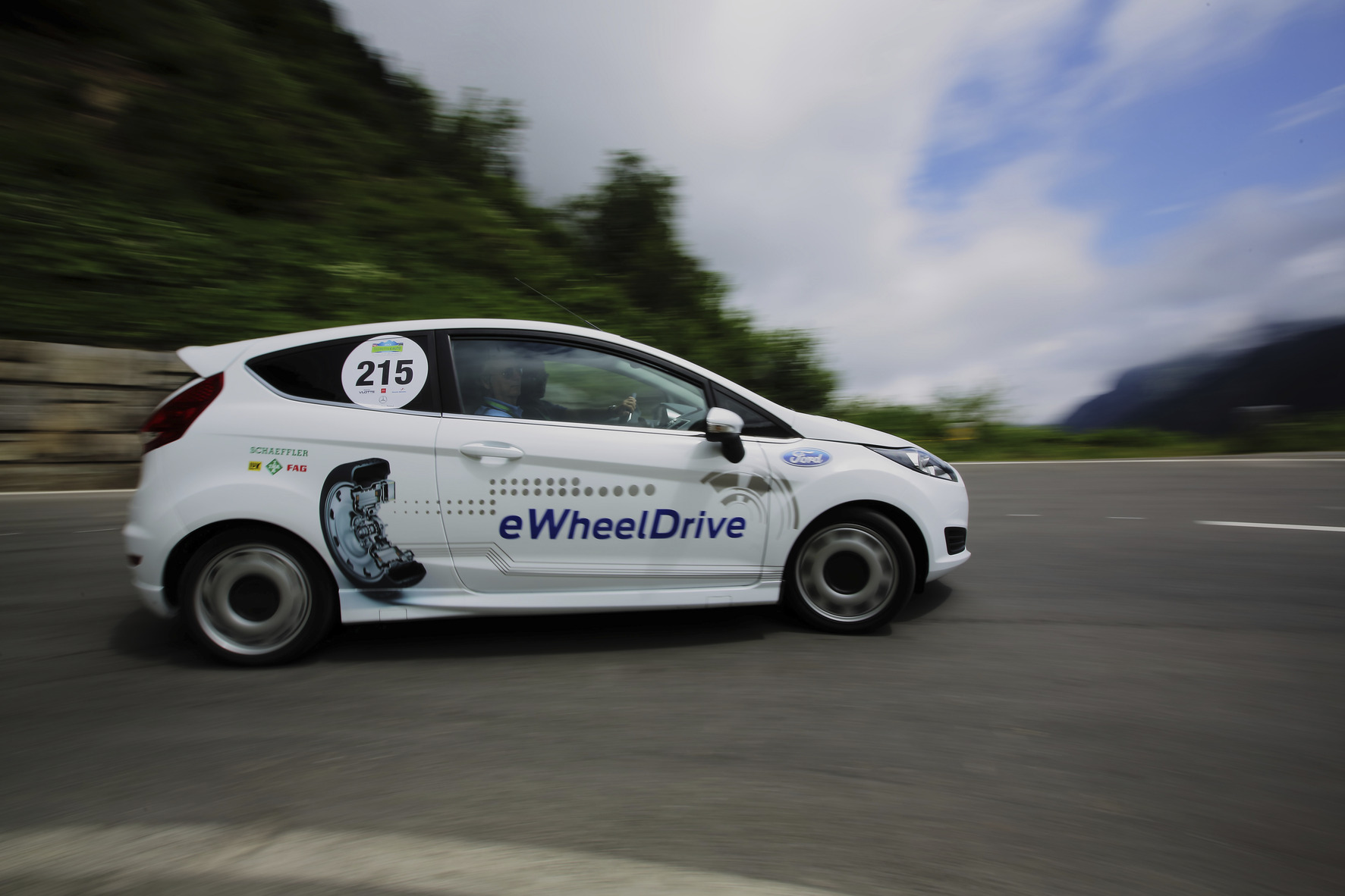
Schaeffler took into consideration the experience gained from this pre-production model during further development of the wheel hub drive. The main focus was on fulfilling customer requirements for higher torque and achieving a higher level of integration. Since 2013, tests have been carried out on a further wheel hub drive jointly designed with Ford. We are reporting about the design and initial results from the driving dynamics tests in this article.
Concepts for an electric wheel drive
In principle, the drive force produced by one or more electric motors can be transmitted in different ways. Traction motors integrated into the transmission dominate in the hybrid and electric vehicles currently produced. Schaeffler has developed a hybrid module to volume production readiness, which will be presented in a separate article [2]. Schaeffler is also currently testing the potential of a range extender transmission [3].
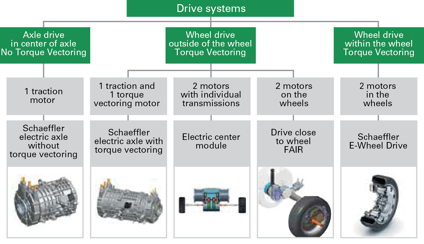
There are a number of different topologies for wheel drives (Figure 1). Conventional electric drives are currently designed as center drives. Schaeffler is currently developing a volume production capable center drive solution to volume production readiness [5]. The electric motor can be used in combination with a lightweight differential to control the distribution of torque to individual wheels. This type of electric axle is particularly suitable for sporty electric vehicles and vehicles suitable for covering long distances with a plug-in hybrid drive.
Wheel hub drives have been used until now in small-volume production in commercial vehicles, urban buses and in the military sector. Wheel hub drives are currently only found as prototypes in passenger cars. There are a large number of solutions, in which two separate motors fitted in a center housing arrangement each drive a wheel via side shafts. This solution is not preferred by Schaeffler because the significant advantages offered by the wheel hub drive (such as the very efficient use of space and high level of maneuverability) cannot be completely utilized. Schaeffler is using a highly-integrated design of wheel hub drive for future city vehicles, in which the wheel becomes a power module. At the same time, drive systems positioned close to the wheel are also being tested as part of research and advanced development projects. Two examples of projects are mentioned, which pursue different approaches with the drive positioned close to the wheel.
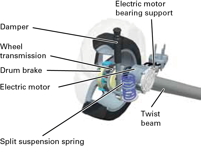
In the “FAIR” project [6] carried out jointly with BMW and the Deutschen Zentrum für Luft- und Raumfahrt (National Aeronautics and Space Research Center of the Federal Republic of Germany) a gear system was integrated into the wheel to reduce the speed of the electric motor mounted on the vehicle in front of the wheel and to decouple the vertical motion of the wheel from the drive (Figure 2). As part of an advanced development project, a variant was tested at Schaeffler, in which the drive motor is supported using a split suspension spring and connected to a transmission via a short side shaft (Figure 3). This means the motor only moves in step with the spring motion of the wheel to a reduced extent.
The following sections of this article focus on wheel hub drives, which in our opinion are the most suitable drive arrangement for electric city vehicles.
A new generation of wheel hub drive
Design and construction
In 2010, Schaeffler set itself the goal of designing a wheel with a highly-integrated drive, which incorporates the electric motor and power electronics in addition to the conventional wheel components such as the service brake. For the first time there is no requirement for all the pulsed cables laid through the vehicle, which is also advantageous with regard to electromagnetic compatibility. This can also be managed with other arrangements of system components, but results in additional coordination requirements.
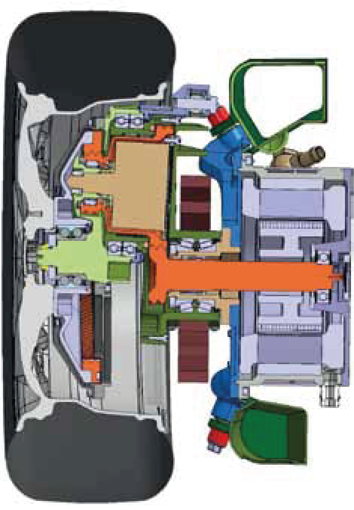
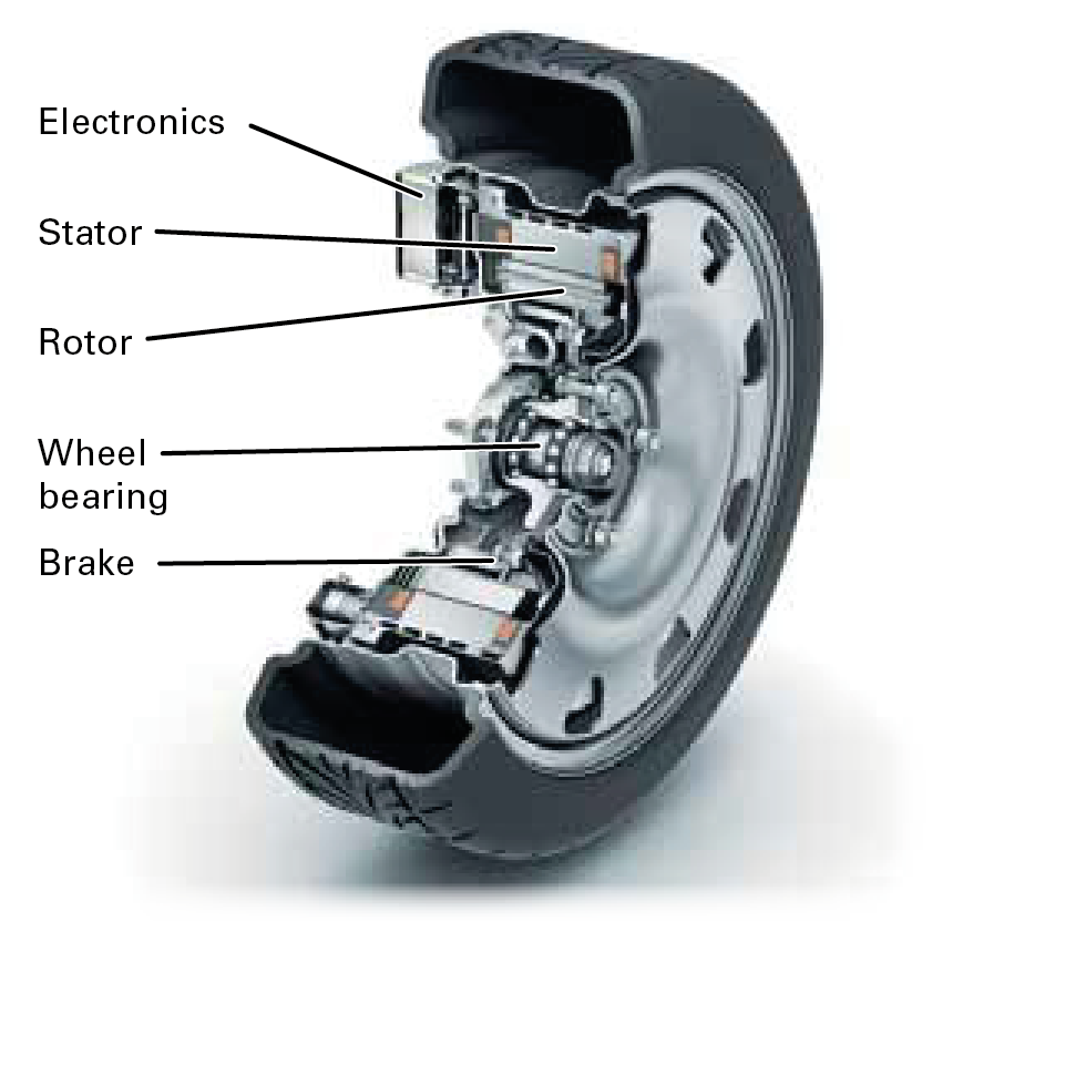
The high level of integration is, of course, a major challenge for development engineers: The total available design envelope is only 16 liters. The task of accommodating the complete drive in a wheel with a 16-inch diameter was solved by carrying out a large number of individual optimization measures (Figure 4). A width of approximately 200 mm gives a conventional tire dimension (195 or 205 tire). The tire corresponds to a volumeproduced tire both with regard to the dimensions and the design. However, the steel rim is a special design, because the wheel disk is connected to the rim shoulder instead of the drop center as in a normal wheel (semi full face). Forged steel rims could be used in a later volume-produced design, which would combine an elegant design with a high load carrying capacity. The hole circle required for screw mounting and centering is compatible with current standard connections.
The entire design has been selected to ensure that a tire change does not cause additional work.
The magnetic gap with a diameter of 278 mm and a width of 80 mm must be maintained within very close tolerances to ensure optimum function of the electric motor. The air gap has a difference in radius of 1 mm. Any tilting, which would allow the stator and rotor to rub against each other, must be prevented in order to avoid corroding surfaces. The wheel bearing is therefore of very rigid design. The rigidity is approximately twice as high as in a conventional wheel bearing. Locking of the wheel if contact occurs between the stator and rotor has been ruled out by carrying out in-house tests. Contrary to frequently expressed assumptions, rubbing does not cause unstable driving dynamics.
Wear does not occur because the dimensions of a rolling bearing do not change significantly during an operating period of 200,000 km. A wheel bearing is also volume production technology, which can be manufactured with current tools and machines.
The modified support plate of the standard drum brake is used to integrate the electric motor into the wheel. The water-cooled stator is supported by the brake anchorplate, which is estende and made thicker in the direction of the outer side of the wheel. The rotor is located on a flange with the brake drum. However, the brake is not omitted but is available as a redundancy level and parking brake. Previous operation of the prototype has shown that even during trips in the mountains (long descents with an 18 % gradient) braking can be carried out with the electric motor only.
The drive unit is sealed with a contact lip seal, which was derived from an industrial application. The seal integrity is in accordance with the standard for wheel bearings so that no moisture can enter even if there is exposure to a high-pressure cleaner. The precondition for this is a corresponding seal design so that it is even protected against high water pressure.
Electric/electronic components
A permanently excited synchronous motor was integrated into the available design envelope, which produces 350 Nm of continuous torque even under unsuitable temperature conditions. The maximum achievable torque is 700 Nm per wheel, i.e. 1,400 Nm for the axle. The starting torque is even high enough to enable the tested prototype with four occupants to start on a 25 % gradient. The electric motor design was selected to ensure a uniform torque output up to high speeds. The total continuous torque is available up to a traveling speed of 100 km/h.
The output of the electric motor is 33 kW (continuous) and 45 kW (peak), whereby this value should not be overestimated and can be calculated from P = m · w directly.
The specified values apply for operation with a voltage of 360/420 V.
Prior experience with the prototype built in 2010 has shown that air cooling is not sufficient to produce the high continuous torque required. This is particularly true if typical automotive worst case scenarios are taken into consideration in the design – for example, a hill start with a low speed at a high outside temperature (40 °C). The decision to design a watercooled unit was made at an early stage for this reason. Cooling is carried out with conventional coolant based on glycol. The coolant firstly flows through the power electronics and electric motor stator and then reverses and is returned in a counterflow process. The drive contains a low volume of coolant. The normal air/water heat exchanger, which is also fitted in the front end of vehicles with an internal combustion engine, is used as a heat exchanger.
The electronic components required for control are also fitted in the wheel. This applies for the high-voltage power electron ics as well as the low-voltage motor control system. The arrangement of the power electronics has been selected so that only a very small distance must be covered by pulsed cables to the electric motor.
The drive is only controlled locally in the wheel to a limited extent. The torque requirement is passed from the general control unit, on which the driving strategy is stored, to the controller in the wheel, which is responsible for controlling and monitoring the electric motor. Requirements with renard to driving dynamics are placed by the vehicle’s safety computer and also implemented in the wheel.
Test stand runs
The drive was firstly put into operation on a test stand before it was integrated into the vehicle. The control system is initially adjusted to match the electric motor and power electronics. At the same time, characteristics such as efficiency, continuous and peak torque as well as the thermal behavior of the system are defined (Figure 5).
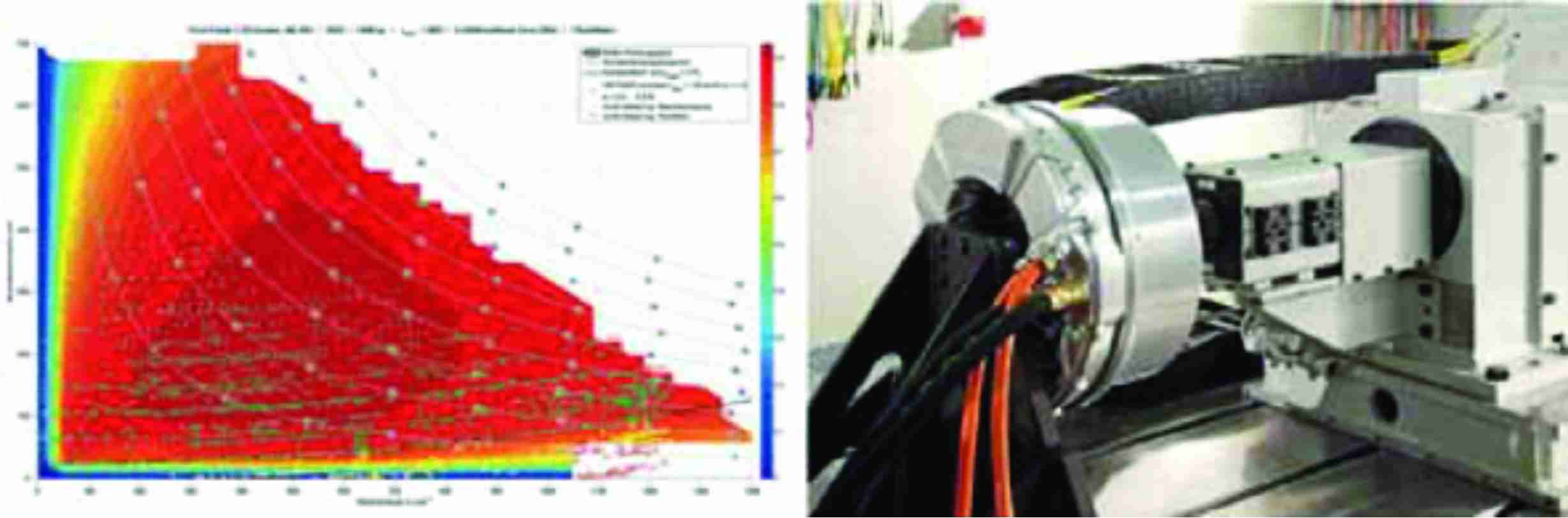
After initial operation, strength and rigidity tests were carried out on an internal drum test stand specially developed for this purpose at the Fraunhofer LBF in Darmstadt (Figure 6). The drive is mounted on a hexapod and placed on the internal surface of a rotating drum. The drum is provided with lateral thrust ribs, which can be used to apply lateral loads to the wheel similar to the contact with a curbstone or when cornering sharply.
The aim of the tests was to check the lateral rigidity in order to ensure no rubbing occurs between the stator and rotor even under extreme lateral loads. The tests have also shown that no rubbing occurs between the stator and the rotor even with increased air pressure and a load that causes destruction of the tire.
Vehicle integration
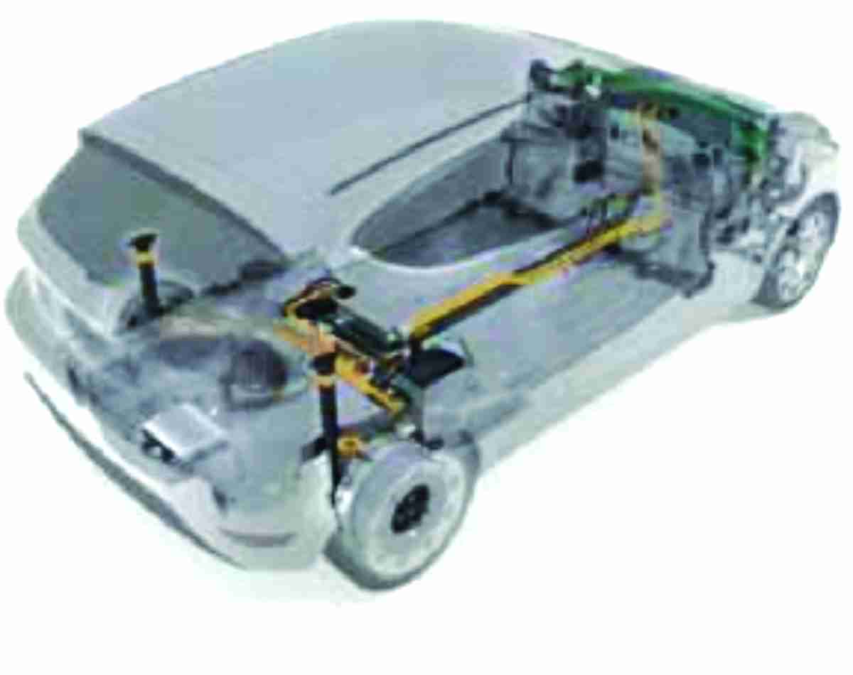
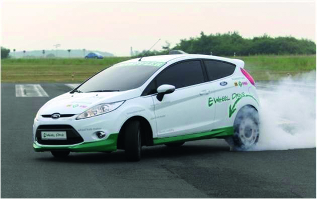
A Schaeffler wheel hub drive at the current level of development was fitted in a Ford Fiesta used as a test vehicle in collaboration with the Ford Research Center Aachen (Figure 6). The high-voltage battery is integrated into what was previously the engine compartment. In addition to the fitting of high-voltage components, the adjustment between the engine and vehicle control system involved a significant outlay. In particular, the restbus simulation, i.e. the simulation of signals for ometted components such as the internal combustion engine by means of software is very challenging. In addition, essential chassis components such as the suspension and damping were adjusted to match the characteristics of the drive. The system weight for the complete wheel hub drive is 53 kilograms per wheel. It must be taken into consideration that the total vehicle weight is not increased compared with an identical vehicle fitted with a diesel engine (1,290 kg empty). This includes a lithium-ion battery with a nominal capacity of 16.2 kWh. The axle load distribution is also the same as the volume-produced vehicle.
A variety of driving dynamics tests were carried out with the test vehicle at a testing site. The tests showed that the prototype was at least equal to a comparably driven volume-produced vehicle up to a speed of 130 km.
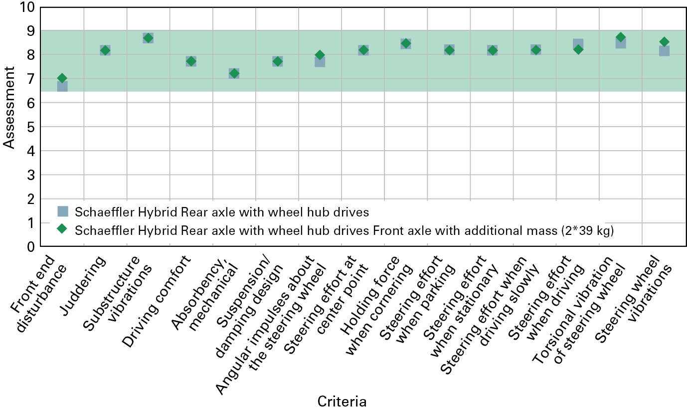
Figure 7 shows the results of driving dynamics analyses with the preceding prototype (Schaeffler Hybrid) because the front axle was included in the tests along with the assessment of the rear axle. The driven maneuvers are plotted on the x-axis, the assessment determined for the vehicle is plotted on the y-axis. Zero stands for “unsalable”, the top mark ten for the perfect vehicle. The original vehicle is in the range 6.5 to 9.
The criteria used refer, in particular, to vertical and lateral dynamics as well as the steering reactions. All assessments are within the range of results for the volume produced vehicle. In this context, it must be emphasized that this driving behavior is only achievable with a spring damping system that is adjusted for higher masses. The modifications were carried out both in the Schaeffler Hybrid and in its successor vehicle, a Fiesta, using volume-produced components.
The results are significant under the aspect that the drive system operates on a twist beam – an axle design which was not originally designed for this drive.
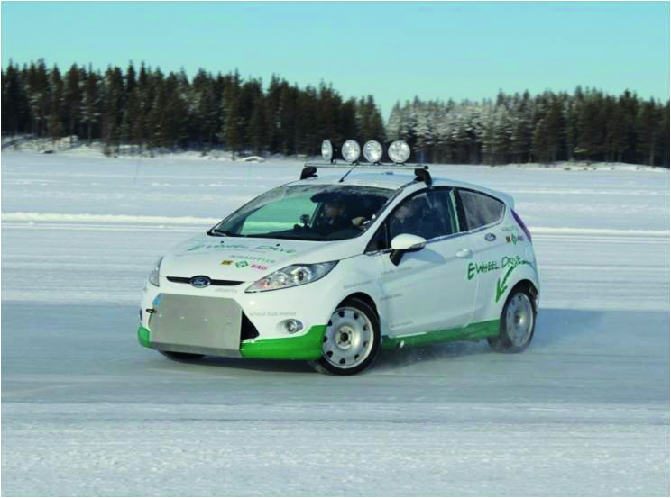
Significant increases in performance were noticeable during some maneuvers which use the potential of torque vectoring. For example, the speed was increased by 10 km/h during a standardized double lanechange maneuver test with the cones spaced at 18 meters. After carrying out initial operation of the drives, a slip control system was applied as a basis for adjusting the torque vectoring and ESP functionalities. The high torque output of the drive system is actively used by a suitable control system for stabilizing the driving behavior. Winter testing was also carried out in North Sweden during February and March 2013 (Figure 9). The tests showed that the function of the drive is even ensured in wet and adhesive snow and at temperatures down to -33 °C. The vehicle also benefits from the selected concept, which does not require a hydraulic system and transmission.
Future developments
Further development of electric/electronic components
Development of the wheel hub drive is currently underway at Schaeffler. A modified electric motor from the industrial sector is used in the current prototype, which is primarily optimized to produce a high torque output. Schaeffler is developing an electric motor specially matched to the requirements of the wheel hub drive for the next development stage.
A continuous torque of 500 Nm per wheel is required for a vehicle with the total weight of the presented prototype (approximately 1.5 tons) in order to transmit sufficient drive force in all driving situations. A further increase in torque density is therefore the objective of Schaeffler’s development. The next generation of the wheel hub drive will be designed to fit inside an 18-inch wheel, which is a conventional size for the vehicle class under consideration.
The efficiency of the motor must still be increased at the operating points relevant for the driving cycle. The acoustic properties for vehicle applications are also in need of improvement. Work will be carried out on these specific points for the next evolutionary stage.
The situation with regard to power electronics is similar. The electronics developed for the prototype in collaboration with the Fraunhofer Institute for Integrated Systems and Device Technology IISB have operated so far without failure. However, these electronics would not fulfill a typical specification used in automotive manufacturing.
Schaeffler is following a modular strategy for the further development of electric components for hybrid and electric drives, so that other drive variants such as the hybrid module or electric axle can be delivered with designs that are as similar as possible in order to rapidly achieve a significant unit cost degression with future volume production orders.
The MEHREN research project
In the MEHREN research project (Multimotor electric vehicle with highly efficient use of space and energy, and uncompromising driving safety), Schaeffler is already working on the next generation of wheel hub drives in conjunction with Ford and Continental as well as the RWTH Aachen University and the University of Applied Sciences in Regensburg [7]. The focus of this project is on the implementation of a new software architecture matched to the requirements of wheel hub drives. This should, in particular, allow optimized cooperation between the electric motor and service brake. The importance of functional safety is also taken into account in a special subproject. The MEHREN project should also show for the first time what potential exists for new vehicle architectures if the wheel hub drive is used as a standard drive from the start of development. A virtual prototype of a purpose-built vehicle will be developed by 2015.


