
Where higher speeds, higher quality and higher thrust loads are present, bearings can face this challenge offering increased features and solutions. The stacked TS bearing assembly, has been developed by Timken just for this type of application.

Humans have followed the Olympic motto “citius, altius, fortius” – faster, higher, stronger – throughout the centuries, continuously challenging themselves to achieve more and do better. But the challenge is not only for humans: Faced with competitive and environmental forces, industrial development has demonstrated the same tendency for decades – and economic criteria dictate its survival.
Translated into bearings language, the challenge becomes the generation of higher speeds, higher quality and higher loads. For example, extruder applications require a reliable bearing solution for high thrust loads within a limited space – namely, their small bore and especially their small bearing outer diameter.
Within this context, an increased number of solutions claim to possess specific features that will address such challenges. One of these, the stacked TS assembly, has been developed by Timken just for this type of application. Its development was initially based on experience and knowledge gained from the well-known 2TS-TM bearing (the tandem TS arrangement assembly) shown in Figure 1. This is one of the basic mounting arrangements for spacer assemblies and has been used successfully in applications such as hydrostatic axial piston pumps and motors, where significant thrust loads are already present.
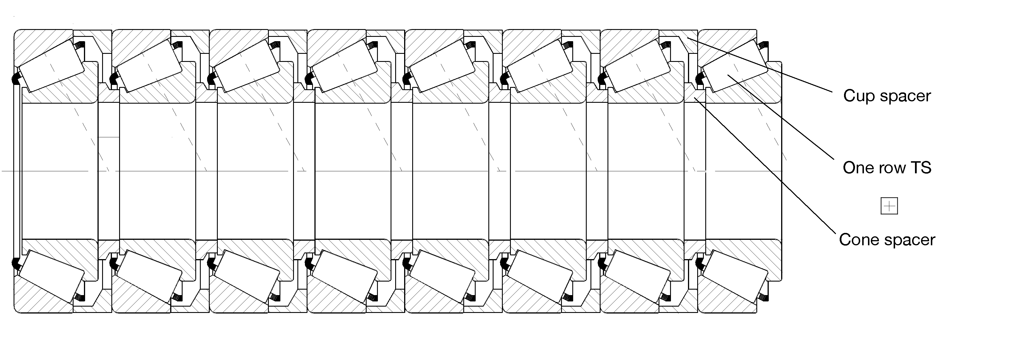
The stacked TS assembly is a variation of the tandem mounting that uses an increased number of rows (Figure 2). It can be applied in situations where a classical thrust bearing solution will not work (for example, when increased thrust loads are present and the envelope constraints are very strict). The challenge for the TS assembly then becomes how to equally distribute the thrust load onto the respective number of rows.
In a simplified approach, the spacers perform like simple springs, with a characteristic stiffness in the axial direction, which depends upon the Young modulus value and the ratio of their section to length.
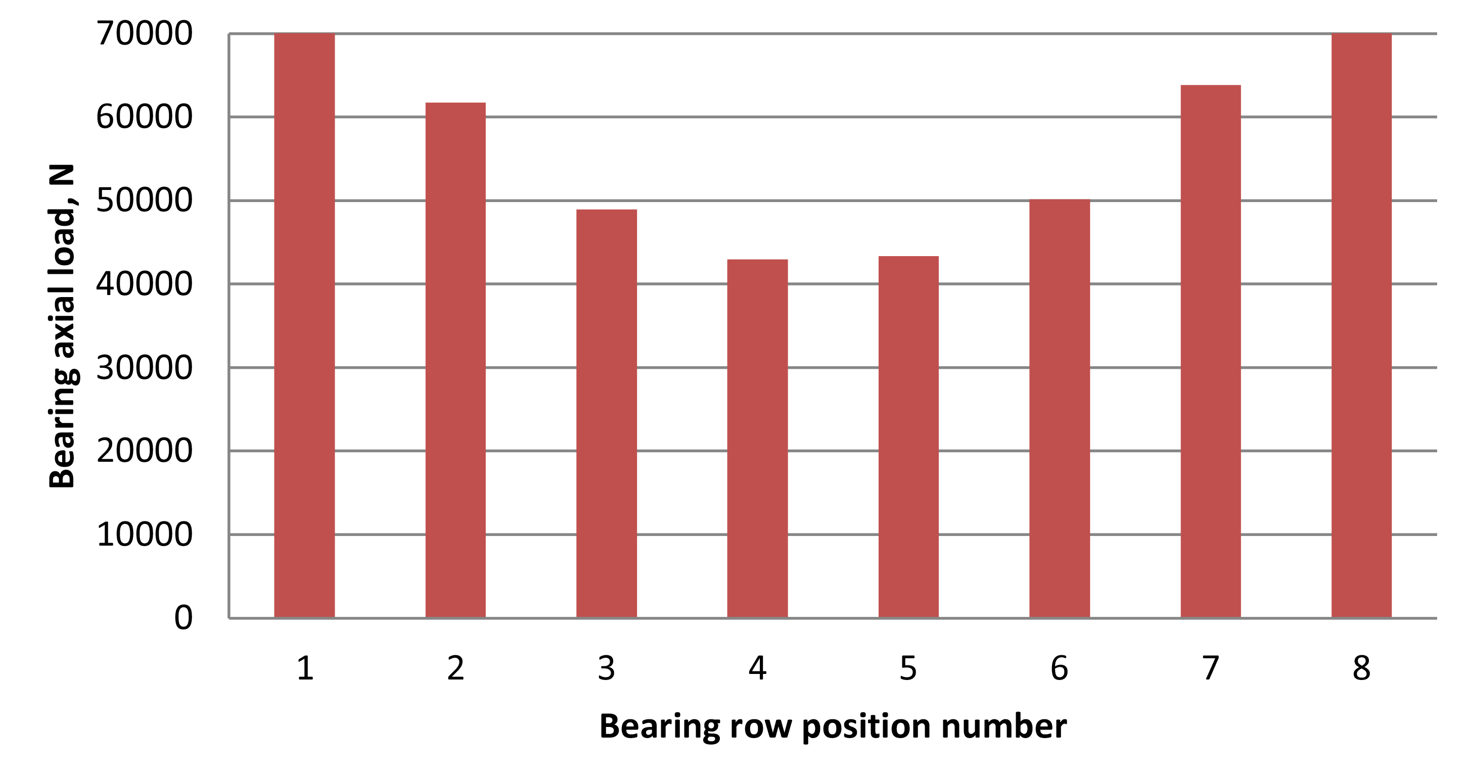
The bearings and the springs constitute an assembly possessing complex stiffness. Consequently, it follows that if the line-to-line (zero) setting is used in all loops for both cones and cup spacers, the load will be distributed unequally throughout the rows – the first and the last row being the most loaded (Figure 3).
If the calculated life exceeds the customer’s desired target life, the application can be assumed to be adequate and the calculation may be completed at this point. As a reference, the calculated life can be the system life, if the system approach is used, or the individual calculated life for each row, if the customer chooses to replace only the failed bearing within the stacked assembly.
Two additional calculations for longer life
However, if the application requires longer life, Timken has developed two additional calculations to determine the effectiveness of the stacked TS assembly:
- The first method, based on identical cone and cup spacers (according to Figure 1), solves the issue of distributing an equal load onto the stacked rows through a differential axial setting (endplay or preload) specific to each of the two adjacent bearings (one loop). The setting value depends upon the applied load, the number of rows, the loop position and the spacer’s stiffness. This is the most commonly used method, applied when the axial load has a unique value. The advantages are its simplicity and the uniform design of the spacers.
The single disadvantage is the presence of a load cycle, since the bearings are set for only one condition. This is overcome in practice by designing the stacked assembly for the most loaded condition of the cycle. In this case, the load will be equally distributed between the rows; for the other conditions, the rows will be unequally loaded, but because the total load is smaller, the specific load on each row should be acceptable. The stress level can be verified with the bearing weighted life calculation and, eventually, through the roller-race contact stress check. The application can be enhanced by adding a supplementary bearing row.
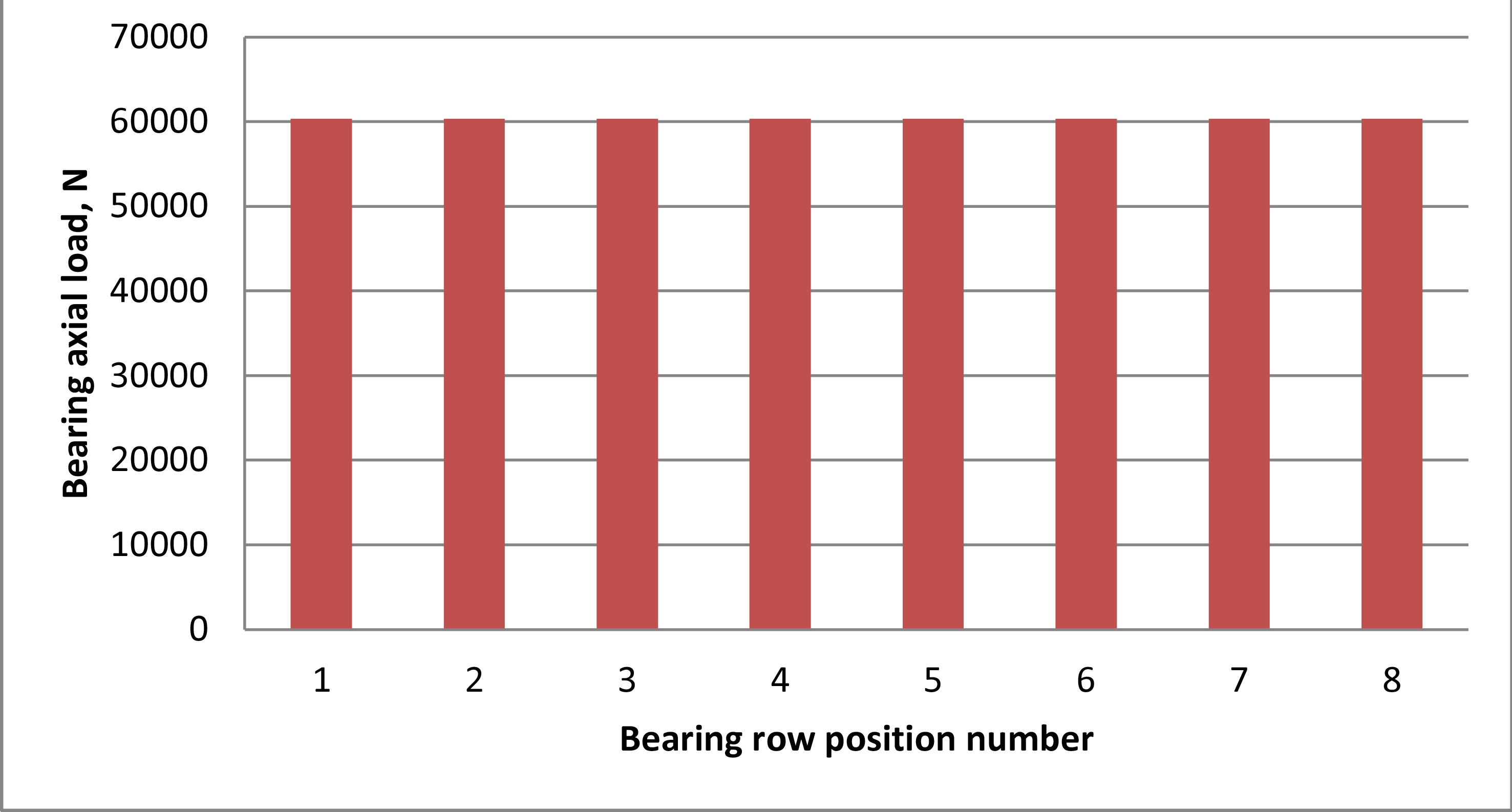
Fig. 5 – Load distribution on bearing rows for differential axial setting.
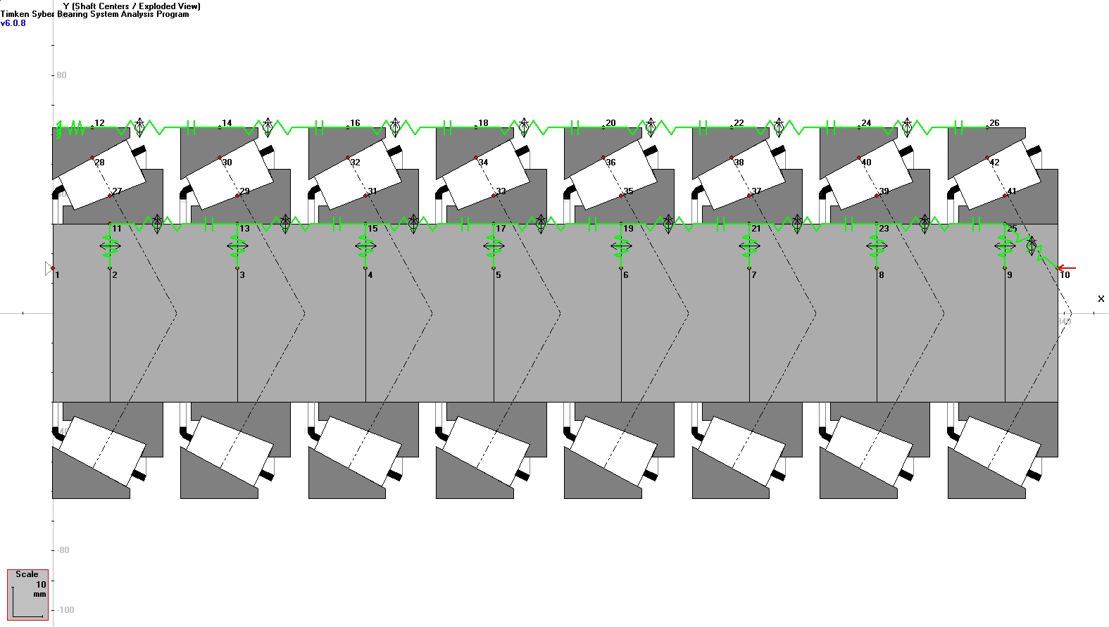
- The second method consists of calculating a ratio between the cone and the cup spacer within the same loop as a function of the number of bearing rows and the loop position. The big advantage of this method is that it doesn’t depend on the load or setting. However the second solution requires designing specific spacers for each row, a challenging design constraint, when the number of rows is large. Timken uses its proprietary calculation program, SYBER (Figure 4), for the validation of the stacked solution – especially for the load distribution check, life calculations and stress validation. SYBER efficiently analyzes complex bearing arrangements and combinations, and Timken application engineers use it daily to support their research.
Figure 5 shows the calculated bearing axial loads in each row, when optimizing the spacer stiffness ratio.
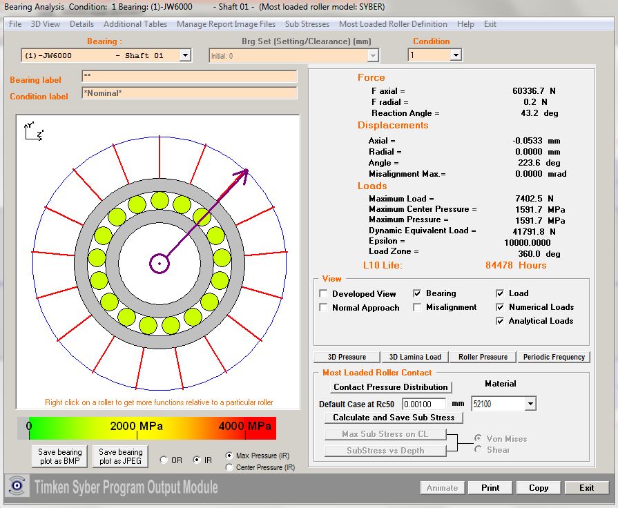
Fig. 6 – SYBER results screen containing general results data for one bearing row.
To approximate real-world conditions as closely as possible, typical load-bearing calculations range from simple to complex. They may begin with a simple hand catalogue calculation of the bearing TS assembly rating (a single TS bearing selection based on the appropriate rating, available geometry, number of rows calculation and target life) and go all the way to complex SYBER modeling including shaft, housing, bearings and all the other necessary elements like spacer stiffness, specific settings, fittings practice, temperatures, lubrication data, etc. Our customers are provided with all calculation details for each row, including load zone, life, load (Figure 6), roller contact stress and many others.
Conclusions
In conclusion, current market developments in areas such as oil and gas, primary metals, aggregate and mobile industries are creating an increased interest in and need for the stacked TS assembly. This extremely versatile solution, a product of the vast experience and expertise of Timken engineers, represents another significant step for the future of bearings and their application.


