
Why are some machines louder than others? Why does the bicycle wheel valve position at the bottom if you let it rotate freely? Why does the car’s steering wheel vibrates at certain speeds? Almost daily, we come across with a phenomenon whose consequences are often underestimated: the unbalance.
The term unbalance derives from balance. A scale is balanced when both pans bear the same weight. Likewise, the weight distribution of a rotor referred to its axis of rotation can play an important role, and an uneven distribution of masses is the unbalance. During the rotation, the unbalance generates centrifugal forces, vibrations, and noises that dramatically increase as the number of revolutions grows.
Operational duration
Bearings, suspensions, housings, and foundations can strongly be stressed by the vibrations deriving from the unbalance, and therefore they may be subjected to a higher wear. Products with unbalanced components often have a shorter life span.
Safety
Vibrations can affect the tightening of bolts to the extent of loosening components. Electrical switches are disturbed by vibrations, and cables can be damaged near connections or fixturing. As a result, unbalance can significantly decrease the safety of a machine, putting operators and the machine itself at risk.
Quality
The finishing of a workpiece in a machine tool can negatively be affected by vibrations. A grinding machine or a woodworking machine, for instance, operates in a less accurate manner and can produce more scraped parts if the spindle and cutting tool have not been balanced in a precise manner.
Competitiveness
The quiet operation of a rotating machine always represents a criterion for the quality assessment, and it can positively affect to the competitiveness of a product: a noisy home appliance or car are products that likely won’t be successful on the market—except for a few edge cases, e.g., sport cars. Noise is generated by the unbalance, making the balancing process a critical procedure.
Types of unbalances
Unbalances can be divided into various types, according to their effect. In addition to the shape and function of a rotor, the type of unbalance influences the position of correction planes and how to split the balancing tolerance. There are three types of unbalances:
- Static unbalance
- Couple unbalance
- Dynamic unbalance
Static unbalance
If you let a bicycle wheel spin freely, you will notice that the valve tends to stop in the bottom position. This happens since the “heaviest” spot tries to place itself below the axis of rotation, in this case by the wheel hub. This type of unbalance is visible even without rotating the rotor, and for this reason, it is called “static unbalance.”
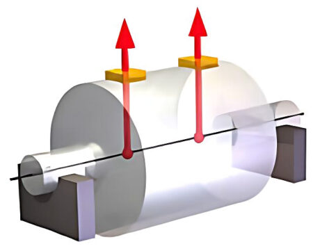
In general, we speak of “static” unbalance when the rotor’s axis of rotation does not pass through its center of gravity. Static unbalance can be corrected by acting on a single point (adding or removing weight) in order to bring the center of gravity back to the axis of rotation. Returning to the example of the bicycle wheel, to eliminate the imbalance, we should put a weight equal to the valve on the opposite side of the wheel. In reality, the wheel of the bicycle rotates at such low speeds that it is not necessary or useful to balance it, which is why these wheels are typically not balanced.
Typical rotors that present predominantly static imbalance are the “disc-shaped” parts where the thickness of the rotor is considerably smaller than the diameter: examples are pulleys, fans, brake discs, and grinding wheels, etc.
Couple unbalance
We speak of a couple unbalance when the rotor’s rotation axis is inclined to the ideal axis but passes through the center of gravity of the rotor. This type of unbalance can be described by considering two equal weights positioned axially on opposite sides of the rotor and at 180° one another.
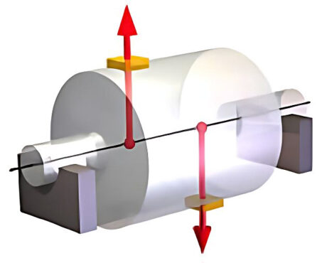
The effect of this type of unbalance appears only when the rotor rotates: in fact, placing the rotor on two “knives” the rotor does not move. When the rotor turns, these masses cause a “couple” (hence the name of the unbalance) which depends not only on the distance of the weight from the axis of rotation (radial) but also on the axial distance from the center of gravity: for this reason the couple unbalance is more appreciable with cylindrical rotors than with disc-shaped ones.
To correct the torque imbalance, it is necessary to intervene on the two opposite planes, effectively “straightening” the axis of rotation until it coincides with the ideal axis.
Dynamic unbalance
By dynamic unbalance we mean an unbalance given by the composition of the static and couple unbalance. The axis of rotation of the rotor is both inclined (couple unbalance) and not passing through the center of gravity of the rotor (static unbalance).
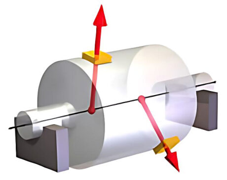
The dynamic unbalance can be described with two weights on two planes of your choice (represented in the figure by two arrows), generally at different values and angular positions. In this case, we speak of “dynamic unbalance” because it can only be determined by turning the rotor. As for the couple unbalance, correcting dynamic unbalance requires acting on at least two planes. Typical rotors that present dynamic unbalance are the armatures of electric motors, centrifugal fans, textile or paper mill cylinders, and compressor rotors.
Schenck, the whole balancing world
Everything rotates must be balanced: grinding wheels, crankshafts, or turbines for power plants. Schenck offers a complete machine portfolio to cover all rotating and oscillating components and assemblies, ranging from a tiny rotor weighing just a few grams (i.e., a dental turbine) up to steam turbines weighing nearly 400 tons.
Schenck proposes solutions for various sectors, like the automotive, oil&gas, aeronautical, and aerospace, and machine construction industry.


