
Tobias Schulze –
In the last years, many different design concepts for drive trains in wind turbines were developped. What is the best way for a good design?
The calculation of gears especially planetary gears can just be carried out by the consideration of influences of the whole drive train and the analysis of all relevant machine elements. In this case the gear is more than the sum of its machine elements. Relevant interactions need to be considered under real conditions.
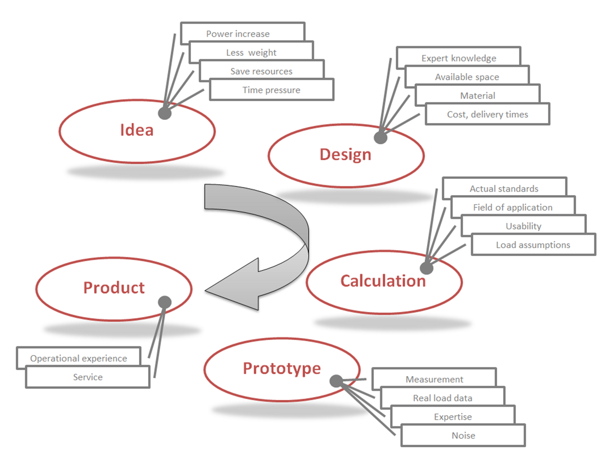
The standardized calculations are for the safe dimensioning of the machine elements with the consideration of realistic load assumptions decisive. But they need to be completed by extended analysis of load distribution, flank pressure, root stress, transmission error and contact temperature.
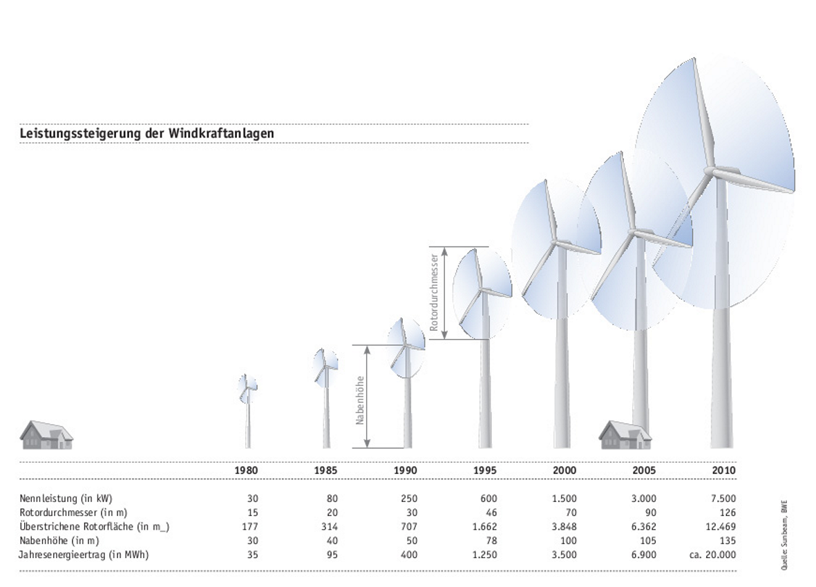
In the last years, there are many different design concepts for drive trains in wind turbines. Today we have a wide area of design from simple 3- stage helical gear sets to the standard design with a combination of planetary-/helical gear sets. New innovative designs – i.e. with stage planets, differential planetary or multi stage helical gears are looking for the optimum of mass by simultaneous increase of power output.
The following chapter shows the most popular and innovative design and compare the advantages of the variants.
Actual gear designs of wind turbines
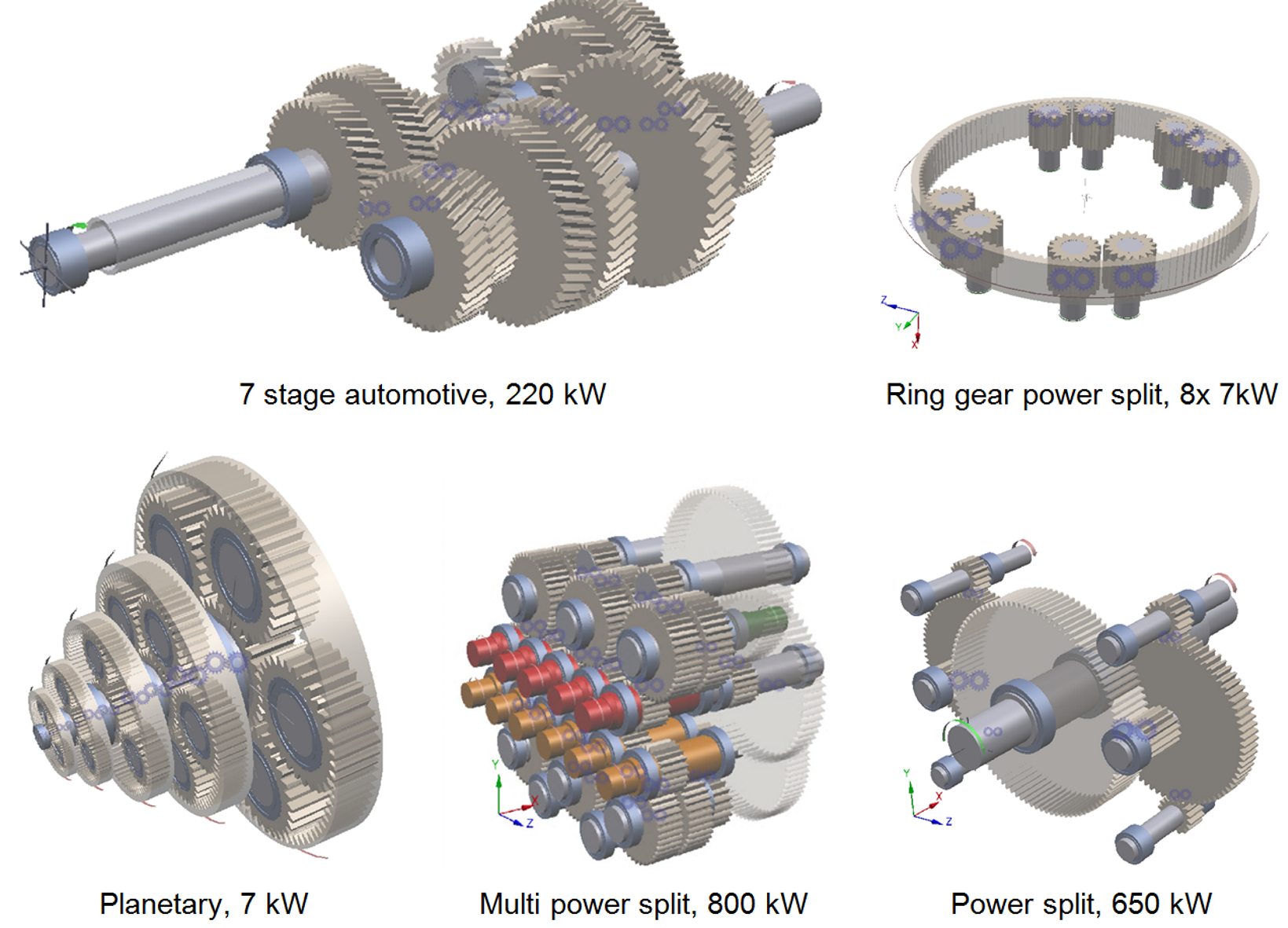
From the beginning of the modern wind turbines – the drive trains where mounted with spur or helical gear sets (2 or 3 stages). These gearboxes are developed for standard industrial applications. There was no customizing for special wind turbine behavior (Fig.4).
The power output for this design concept reach 750 kW and is also used in existing turbines up to date, mainly in the Asian region. Combined with the stall concept for the rotor blades result this design in a very easy turbine handling for robustness operating.
The next step in the development is the replacement of the first helical gear stage with a planetary gear stage, mostly with three planets. This step makes higher output power level possible. Turbines with 750 kW to 2000 kW are realized (Fig.5).
The using of a second planetary gear stage instead of the spur gear stage was the next development in gearbox design. Turbines with 2500 kW to 5000 kW are realized (Fig.6).
An alternative way by minimize the number of part is the stage planetary concept. An additional ration on the planet axle is realized by a so called stage planet. So much higher gear ratio in only one stage (1,5 stage) is possible. The gearboxes exist with (1,5 stage) and without (2,5 stage, not shown) a center distance (Fig.7).
The opposite way is the differential gearbox concepts. This variant consists of two planetary stages with a power split, one differential and one spur gear stage. The advantage is the weight reduction compared to conventional concepts and the easy service due to modular design. Turbines with 2000 kW to 4000 kW are realized (Fig.8).
The special requirements of offshore wind turbines results in another very interesting concept based only on helical gear stages with a multi-power-split. In general the gearbox has a high power density in combination with a lightweight design. Instead of the classic concept there are two generators on the high speed side for variable power output. Turbines with 6500 kW are realized and up to 12000 kW are planned (Fig.9).
Design steps – best practice
Especially for design concepts of planetary and spur gearboxes the newest development of DriveConcepts the software MDesign Gearbox is established. The calculation can’t replace measurements and test drives, but iteration steps can be reduced economically. The software allows an intuitive and easy handling in the design process of whole gearboxes from the dimensioning of the machine elements – shafts, bearings and toothings, according to the actual standards.
[su_slider source=”media:2617,2618,2619,2620,2621,2616″ link=”lightbox” target=”blank” autoplay=”8000″]
For toothing are implemented:
DIN 3990:1987 T1-T6
ISO 6336:2008 T1-T3, T5 & TechnicalCorrigendum1:2008.
Future work for toothings:
– load distribution according to ISO 6336:2008 Annex E
– micro pitting according to ISO/TR 15144-1
– scuffing according to ISO/TS 13989 1 & 2, AGMA 925
– gear mesh efficiency / loss factor HV & HVL.
The shafts of the gearbox are calculated according to:
– DIN 743:2012 T1-T4 & Beiblatt 1,2.
For the roller bearings different calculations are possible:
– life time LH10 according DIN ISO 281:2009;
– modified life time according DIN ISO 281:2009 Beiblatt 1,3;
– advanced modified life time according DIN ISO 281:2009 Beiblatt 1,3;
– life time according ISO/TS 16281:2009.
So the software allows calculating the system gearbox in one step including a complete documentation into a PDF/A document according to ISO 19005-1:2005.
The following three steps are defined for effective gear design:
definition of gearbox kinematic gearing, bearing and shaft design, planet carrier design housing draft;
optimization of macro geometry deformation and stiffness analysis helix angle and pitch ratio optimization design of planet carrier and housing;
optimization of micro geometry flank modification for optimal load distribution on flank and to planets noise optimization.
Mass or design space optimized. Two difference ways?
MDesign Gearbox is a good solution for mass and design space optimization. Not only has the stiffness optimization led the engineer to a number of detail problems. The search for a mass and construction size optimized gear is a highly complex question, due to the number of overlapping influences.
The mass savings amounts in this example to about 25% in respect to the original design. At the same time the optimization of the construction space amounts to 15%.
What we have learned?
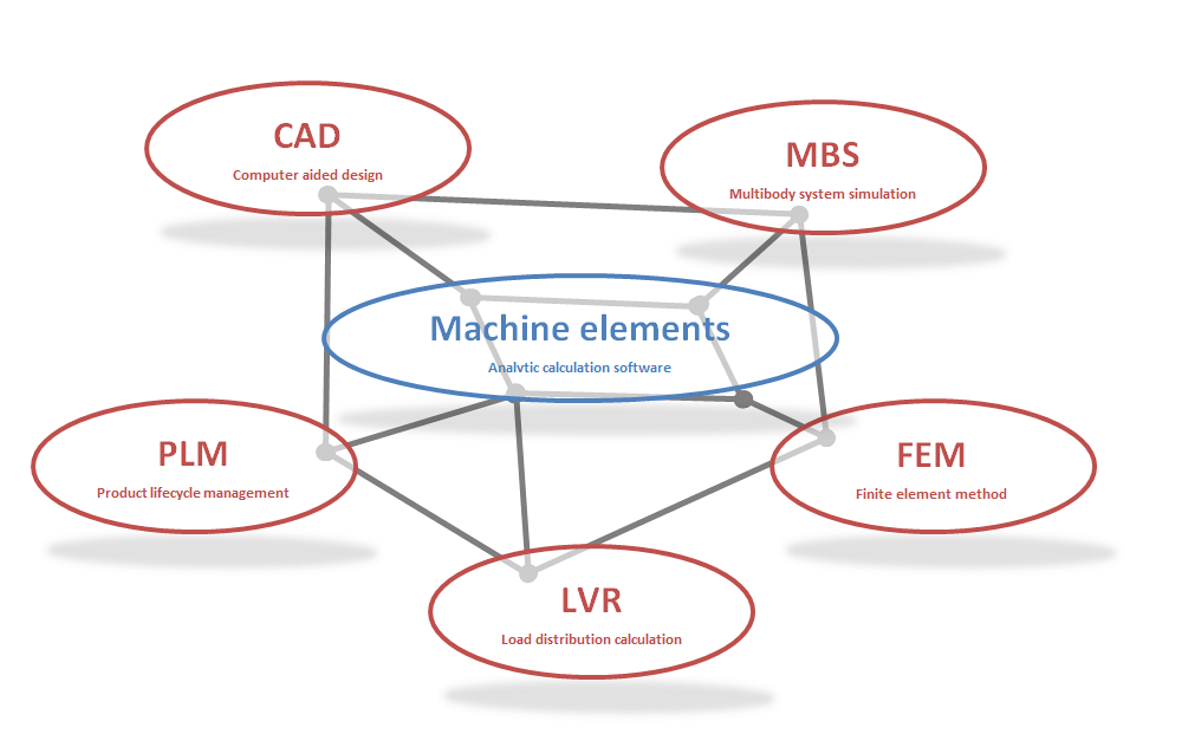
To solve all this calculation tasks in an efficient way it is necessary to install calculation software. To reduce the necessary inputs to a minimum it is indispensable to have a high degree of connections between the single calculation modules. In the background the task is efficiently solved with scientific established calculation kernels and uniform interfaces.
So a fast and secure concept, dimensioning and calculation of the machine element, the gear and the whole drive train are possible. There is the possibility to optimize toothings, shafts, bearings and bolts with use of real load assumption. Using this calculation software already at an early point of the product life cycle (PLC) you can get secure statements of your finish product without manufacturing prototypes.
This calculation can’t replace the measuring campaign and test runs but unnecessary iterations.
SEE ALSO THE VIDEO:
http://www.youtube.com/watch?v=_6BhCVkcJg4#t=13


We are using 2 stage Helical gearbox. Capacity is 250Kw, The design of the helical gearbox is steel body. Each shaft holding bearing both the sides are Spherical roller bearings. Like 22216 -2nos, 22322,22324, 23044,2352 each 1no.
Normally this type of gear box life is 10years from machine / gearbox commssioning. After service the gearbox life is reduced to 4years.
Now we want gear and pinion shaft both sides bearing design will be change for improving gearbox life.
So we want different type of windmills gearbox internal design – bearing used details for our reference.
Kindly send us your reference details and your opinion at the earliest.
Thanks and Regards
M.Murugesan.
MMSREE Engineering consultancy,
Tirunelveli.
Dear Eng. Murugesan,
I thank you for your kind request.
For more information about wind mill gearbox design, you could contact Tobias Schulze to the following address:
tobias.schulze@driveconcepts.com
Kind regards
Anna Bonanomi
Innovation dans le mouvement de la voiture en utilisant une chose facile à faire est la plus grande innovation est non complexe pour les voitures et les avions donc des navires et des appareils modernes les plus populaires
Pour réaliser des projets innovants et un réel succès efficace doit trouver un partenaire ou de participer à des réalisations les plus importantes de la plus sophistiquée
Please sir I want to know can we use two gear boxes in single wind mill
Is it possible or not . If it is possible , what is the drawback for using two gear boxes in single wind turbine
Dear Mr. KAMESWARI,
I am glad you appreciated the content of our magazine Power Transmission World.
For any further information about DriveConcept, you could directly contact Dr. Tobias Schulze:
tobias.schulze@driveconcepts.com
Best regards
Anna Bonanomi
editor
Thank you for all and i am mechanical engineering student and i am doing my final research project (thesis) and i need you to help me because i am working on wind turbine electric generation.
Thank you again!
Dear Amanuel,
I am glad you appreciated the content of our magazine Power Transmission World.
For any further information about DriceConcept, you could directly contact Dr. Tobias Schulze:
tobias.schulze@driveconcepts.com
Best regards
Anna Bonanomi
editor