Michele Gabrio Antonelli, Walter D’Ambrogio, Francesco Durante – Università degli Studi dell’Aquila (Italy)
To satisfy the new requirements of collaborative robotics, not only in industrial ambit but also in the field of medicine and rehabilitation, soft pneumatic actuators, able to reproduce the movement of fingers, have been developed.
Among them, the pneumatic actuator presented here is intrinsically soft due to the silicone rubber constituting it, wrapped by a square knit gauze that contains its expansion and guides its motion through opportune cuts at the joints. A numerical model has been developed for the design of the actuator, which has been implemented and characterized experimentally.
Collaborative robots
In the manufacturing industry, to combine the performances of robots with human skills and to allow the sharing of the same workspace between robots and humans [1], they have introduced collaborative robots that own safety and reliability requisites, needed for the man-robot coexistence and interaction. Collaborative robots have an edge-free light structure and they are often coated by soft materials to reduce the effects of accidental impacts; moreover, they are equipped with force control systems and vision systems while zones of the work volume can be inhibited by software. A specific regulation [1] defines inherent guidelines. Concerning end-effectors, in industrial ambit are used vacuum gripping systems or grippers equipped with two or more stiff fingers with electric or pneumatic drive. Unlike solutions adopted in medical [2] or rehabilitation [3] field, soft pneumatic actuators do not find large use in industry, yet. However, they have developed actuators able to reproduce the movement of human fingers, to be used as gripping devices.

It is possible to distinguish two types of structural solutions: a tube with an opportune shape, made of only elastic soft material; the combination of a tube of soft elastic material with an adequate rigid stiffening. The first solution can be implemented in different ways: the tube can be made with different longitudinal chambers [4, 5]; the tube, with a single chamber, can feature zones with different thickness [6]; the tube, with unvaried thickness, features a flat and a bellows zone [7-9]; the tube can be made by means of two concentric glued films, with different stiffness, among which balloon-shaped reinforcements are inserted [10].
The second solution can be implemented in different manners: the symmetric tube can be combined with an outer rigid gauze, like McKibben pneumatic muscles[11], subdivided into two sectors with different angles of thread interweaving [12]; a single gauze, with the same interweaving angle, is wound around a tube with different thickness and rectangular section decreasing from the proximal to the distal area [13]; a single gauze is wound around a tube with constant rectangular section [14], or one with semi-circular section [15], where a surface is totally coated by a layer of inextensible material. The outer gauze always performs the task of avoiding tube expansions.
The present work is focused on the development of a highly soft pneumatic actuator, at low cost and of easily implementation. The actuator must act as a finger of a collaborative robot and it is made with a silicone rubber tube wrapped in a square knit gauze: opportune gauze cuts, at joints, and the rubber softness generate its bending. The Finite Element numerical model for the actuator design, the actuator prototype and experimental characterization and validation tests are described hereunder.
The numerical model
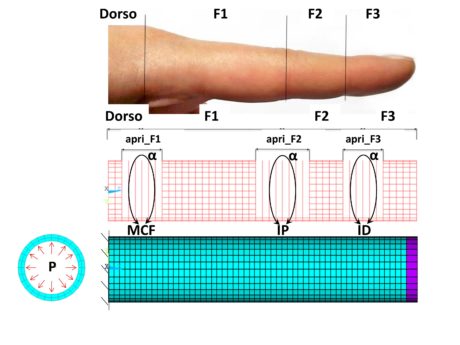
The actuator consists of a silicone rubber tube closed at one extremity and wound by a polyamide square knit gauze (side of 2 mm). When the air space is pressurized, the gauze limits the axial and radial expansions of the tube and guides the motion through opportune cuts at joints. The position along the axis and the circumferential opening of cuts determine the actuator flexion, according to a physiologically correct motion. The behaviour of the actuator is not linear, owing to the non-linear constitutive law of silicone rubber and to the geometrical non-linearity caused by big deformations. The asymmetric arrangement of joints along the tube does not allow treating the actuator as an axial-symmetric structure. Therefore, they have developed a Finite Element three-dimensional model. The hyper-elastic behaviour of silicone rubber has been modelled with the first-order Mooney-Rivlin formulation (c10=0,0694; c01=0,0628; υ=0.46) [11]; the polyamide material of the outer gauze has been modelled as linear isotropic (E=2000 MPa; υ=0.1); the closed extremity of the tube has been modelled as an aluminium plug with linear isotropic behaviour (E= 70 Gpa; υ=0.33), to avoid deformations of the distal surface of the actuator. In Figure 1 is represented the numerical model developed.
In Figure 1 are reported the input geometrical variables of the model: the F1 lengths (of the phalanx), F2 (of the second phalanx), F3 (of the top joint); the axial openings open_F1 (of the metacarpophalangeal joint), open_F2 (of the proximal interphalangeal joint), open_F3 (of the distal interphalangeal joint); of the circumferential opening of the α cut. The value of the metacarpus length, Dorsal, is equal to 10 mm and it does not influence the actuator behaviour. The same value of α has been set for all joints. The constant input geometrical values are the following: outer diameter of the tube =20 mm; tube thickness =2 mm. The size of the elements in axial direction is set as 2 mm; the resulting one in circumferential direction is equal to 2.24 mm (to have a whole number of nodes along the circumference). The thickness of the tube wall counts two elements.
Hexahedral elements have been used for the tube and the plug; rod elements for the gauze. At joints, cuts are modelled omitting the construction of the gauze elements for the entire axial and circumferential extension of the joint. The numerical model does not simulate sliding motions of the gauze with respect to the tube: the nodes of rod elements coincide with the most external nodes of hexahedral elements at the outer surface of the tube. An interlocking constraint was applied at the open extremity of the tube. Pressure was exerted on the internal surfaces of the tube according to a ramp, from zero to a value of 0.30 MPa. Non-linear analyses were carried out with the Newton-Raphson method. Starting from the anthropometric measurements of the index finger [16], different simulations were carried out by varying input geometrical parameters to obtain θ1, θ2 and θ3 output angles, coherently with the angles of the human index finger, where θ1 is the angle of the metacarpophalangeal joint (MCF), θ2 is the proximal interphalangeal joint (IP) and θ3 is the angle of the distal interphalangeal joint (ID). The measured angle coincides with the external angle between the axis of the previous phalanx and the successive one’s. The table reports the anthropometric measurements of the index finger and the optimal values supplied by the numerical model, detected by an image analysis carried out on displays concerning displacement results. Values were achieved for the maximum finger bending, corresponding to a 0.20 MPa pressure. α was equal to 270°.
The comparison of values highlights that θ3 does not satisfy the correspondence with the anthropometric value. This depends on the missing differentiation of α value for the various joints. However, results suggest that such a model will execute a more efficacious closing operation than the real finger. Finally, the anthropometric value of F3 does not consider the soft tissue at the tiptoe that, on the contrary, is taken into account in the numerical model.
The experimental prototype
The actuator prototype, made according to the numerical values reported in the table, is composed by a tube closed at one extremity and by an external gauze. The silicone rubber adopted for the tube is XIAMETER RTC-4250-S; the gauze, with 0.25 mm thickness, is made of polyamide 66. The tube was implemented by pouring silicone rubber, in liquid phase, into a mould made by rapid prototyping. As shown in Figure 2a, the mould consists of two shells mounted on a basement. When the shells are assembled, they form a cylinder cavity inside which is inserted a core featuring such a groove as to implement, at the pouring end, an annular tightening projecting part in the tube. The core height is inferior to the height of the shells to realize the closed extremity of the tube. Closed shells and the basement form a tightened system. During the pouring operation, the mould is positioned on a vibrating plate to facilitate the deposition of the silicone rubber and the removal of air bubbles formed during the rubber processing. When the solidification is accomplished, after the tube shakeout from the mould, the removal of eventual burrs is carried out, Figure 2b, then proceeding to the gauze positioning: a side of it is glued along a line, for the entire tube length, and successively the gauze is rolled up, in two coils, on the tube. During the latter phase, the adherence between gauze and tube must be strictly assured. It is important to obtain a good superimposition of the gauze mesh between the two coils. The free side of the gauze must be placed closed to the glued one for being welded, by polyamide melting, to the underlying layers. The welding is carried out on the entire tube length, in the actuator part not concerned by gauze cuts. A further welding is executed at the closed extremity of the tube, so that the gauze itself acts as a plug. Then, cuts are performed through scissors, according to the values reported in Table 1.
Tab. 1 – Comparison between the anthropometric and numerical values of characteristic finger parameters
| Parameter | Anthropometric value | Numerical value |
| F3 | 15.82 ± 2.26 mm | 20 mm |
| F2 | 22.38 ± 2.51 mm | 22 mm |
| F1 | 39.78 ± 3.13 mm | 40 mm |
| open_F3 | – | 10 mm |
| open_F2 | – | 16 mm |
| open_F1 | – | 12 mm |
| θ3 | 0° ≤ θ3 ≤ 65° | 74° |
| θ2 | 0° ≤ θ2 ≤ 100° | 98° |
| θ1 | 0° ≤ θ1 ≤ 75° | 74° |
The superimposed layers that constitute the joint are welded to avoid relative sliding motions. The Figure 3 shows welding operations and the execution of cuts. The last operation is the assembly of the supply duct at the open extremity of the actuator. The duct is made with a steel tube mounted inside a 3D printed cylindrical bush, equipped with pneumatic fitting for the air input/output. The pneumatic sealing is assured by the annular projecting part inside the tube; the mechanical sealing is performed by an outer strip that tightens the tube on the cylindrical bushing. The experimental prototype of the actuator has the following characteristics: total length=100 mm; outer diameter =20.5 mm; tube thickness =2 mm; tube mass =13g; overall mass =80g. Figure 4 shows the prototype at rest and at the highest deformation.
Experimental activity
It was carried out to test the prototype functionality and to validate the numerical model. The prototype was subjected to preliminary tests to assess the presence of possible air leakages, inclusions of air bubbles in the tube and eventual sliding between the tube and the gauze. It resulted the prototype was integer and the assembly correct. Afterwards, they tested the prototype behaviour according to pressure values: the maximum actuator closing was registered for a pressure value of 0.20 MPa, in correspondence of which joints showed some swells.

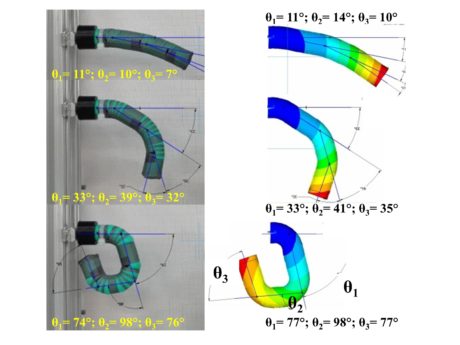
The model validation was carried out through a comparison between the experimental and the numerical values of θ1, θ2 and θ3 angles. The experimental values were obtained through the image analysis of the actuator, photographed for different pressure values; numerical ones, through the image analysis of the displays of simulation results of the numerical model. Experimental tests were carried out in almost static conditions: starting from the null value, pressure was increased by 0.02 up to the complete finger closing. Figure 5 shows three examples of image analysis for the measurement of characteristic angles.
Figure 6 shows the comparison of the trends of experimental and numerical angles, depending on the pressure value. We can notice a good correspondence between experimental and numerical results. Some significant differences are registered for θ3 in the 0-0.10 MPa pressure interval. Such behaviour is probably due to an unsuitable adherence between the closed extremity of the tube and the gauze: the pressure energy does not cause the only bending of the joint but it also allows a modest extension of the top joint. The good correspondence of curves allows stating that no sliding occurs between the gauze and the tube and the hypothesis for which the gauze is rigidly locked is acceptable. According to the results reached, the numerical model is experimentally validated and then it can be used as design tool for that type of actuators.
Conclusions
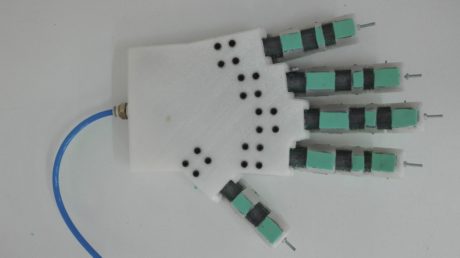
A soft actuator has been developed, to be used as finger for a collaborative robot. The actuator is made with a silicone rubber tube coated by square knit gauze. The actuator bending is obtained through opportune cuts on the gauze, at joints. According to a Finite Element numerical model, they have implemented and experimentally tested a prototype of the actuator, inspired by the human index finger. The technological process proved to be efficacious and easily repeatable. The prototype is light and shows high softness; the behaviour strictly resembles a human finger’s. Currently, a research activity is in progress for the kinetic-static characterization of the actuator and to solve the problem connected with joint swells, at the highest pressures. The final goal will be the implementation of a robotic hand to be applied to a collaborative robot for real applications.
Bibliography is available upon request to the editorial staff: anna.bonanomi@tecnichenuove.com


