
The present article illustrates the study of the kinematic chain between tractor and rotary harrow used for the motion transmission from the PTO to the tool. The study has focused also on the implementation of electronic parametric sheets in order to analyse different working conditions of the tool and its various geometries.
Terenziano Raparelli, Gabriella Eula, Alexandre Ivanov, Giuseppe Pepe
Department of Mechanical and Aerospace Engineering , Turin Polytechnics
The present work is devised in the ambit of a PRIN (Research projects of relevant national interest) research project: ban 2015 “Optimization of operating machines through the analysis of the mission profile for a more efficient agriculture” (duration 2017-2020).
Such research project sets the target of studying the performance characteristics of some agricultural machines to understand their operation at best, in order to optimize their operational performances. In particular, the focus is either on the perfecting of the existing ones or on the development of new solutions in order to extend their life cycle, to limit the fuel consumption and to decrease working times, meanwhile granting optimal levels of tillage.

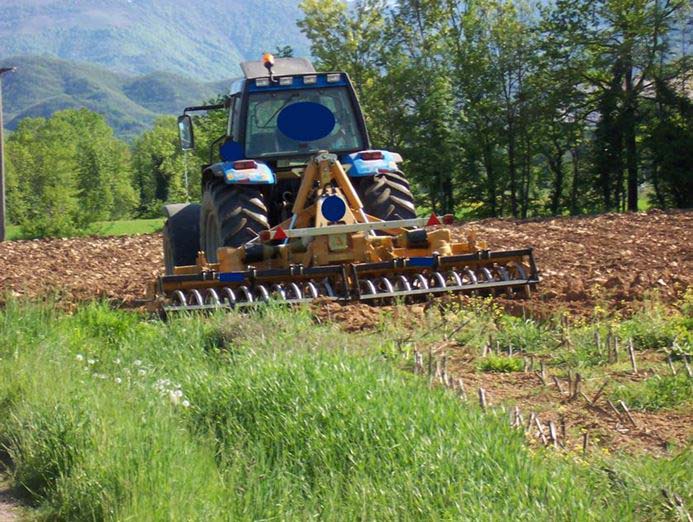
In agriculture, mechanized operations cover different aspects of the agricultural production as they are adopted for the soil cultivation and tillage, sowing and fertilizing. Besides, spraying machines are also used for the distribution of pesticides and machines for the product collection, such as machines for haymaking, harvesting fruits and cereals and so on … [1-3]. The figure 1 illustrates an example of mechanical tillage of the ground.
The operating machines for the tillage include rotary harrows. They are used in operations of refinement and levelling of the seedbed after ploughing, they are often adopted for inter-row actions aimed at controlling weeds in vineyards and orchards.
Rotary harrows are operating machines driven by the tractor and connected with it by three-point hitch. The ground tillage is performed by teeth or knives installed on the characteristic rotating organs of the rotary harrow while a cardan shaft grants the connection between the harrow itself and the PTO – Power Take Off of the tractor, as schematized in figure 2. The present article illustrates the study of the kinematic chain for a rotary harrow operated by a tractor of size 80 – 100 HP.
Kinematic chain for the motion transmission to a rotary harrow
The figure 3 shows the CAD modelling of the kinematic chain under study, composed by: a power take off (1), a cardan shaft (2), a safety joint (3), a speed reducer (4), a series of toothed wheels (5) constituting the rotors where are fixed the characteristic knives (6) of the rotary harrow [4].
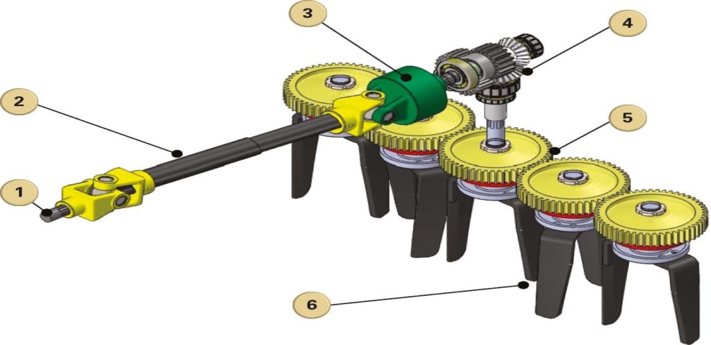
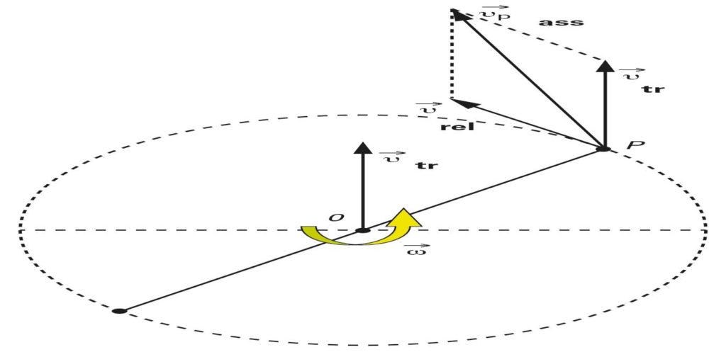
The knives represent the terminal chain elements that interact with the ground, therefore the analysis of their motion during the soil tillage is of notable interest. The overall motion is the consequence of the advancement motion of the tractor, which drags the entire harrow, and of a rotation imposed by the PTO to rotors, that is to say to knives. In figure 4, it is possible to observe the composition of the absolute speed of the P point, representative of the knife of the rotary harrow, as contribution of the relative component and the drag one.
The track travelled by the single knife, in case the module of the drag speed is equal to the module of the relative speed, performs a cycloid trajectory, that is to say the curve described by a fixed P point of a circumference that rolls without sliding along a straight line. The Cartesian coordinates (X, Y) of P written in parametric form are the following:
Y = r (ϑ – sin ϑ) (1)
Y = – r cos ϑ (2)
Where ϑ represents the rotation angle of the rotor and r the radius.
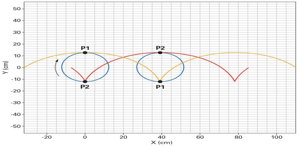
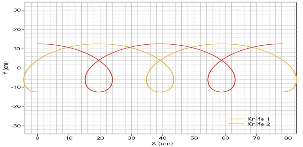
Fig. 5 a) Cycloids of points P1, P2 with pure rolling motion; b) example of real trajectories travelled by the operating organs.
In the figure 5a are reported the trajectories travelled by the two knives (P1 and P2) fixed to the rotor, represented by the blue circumference, for a motion of pure rolling of the latter (r = 125 mm). In that figure the trajectories of the knives are characterized by a cycloid arc that repeats at each complete revolution (ϑ = 2π) of the rotor, by an arc length that is four times the diameter, maximum height equal to the rotor diameter while the base is equal to π times the diameter. Moreover, it is possible to observe that the two trajectories are out of phase each other by ϑ = π because the knives are mounted opposite each other.
In the real operation of the harrow, the advancement speed of the tractor imposed at the centre of the rotor is inferior to rϑ, speed corresponding to the pure rolling: for that reason, the real trajectories run by knives during the ground tillage are modified according to the trends reported in figure 5b. In that figure, compared to the 5a, it is possible to observe that, with the same X advancement of the harrow, the number of revolutions performed by the rotor increases: this results in more tillage of the ground. For that reason, an optimal choice of the advancement speed allows reaching the desired tillage degree of the soil.
Tooth – ground interaction
As above said, the only organs of the machine working the ground are the rotors that include teeth: therefore, it is very interesting evaluating the forces exchanged with the ground. The knowledge of this piece of information allows tracing back the actions exchanged among the various organs of the kinematic chain analysed, up to the PTO.
The analysis of the tooth-ground interaction based on the knowledge deriving from literature [5-7] allows estimating the force exchanged between the ground and the equipment through the relation:
D = Fi ∙ (A + B ∙ S + C ∙ S2) ∙ W ∙ T (3)
proposed in [5] where:
- D equipment drag force (N)
- Fi dimensionless parameter of the ground, subscript i: 1 fine structure, 2 medium structure, 3 raw structure
- A,B,C specific dimensionless parameters of the tool
- W equipment work width (m)
- T tillage depth (cm)
- S advancement speed (km/h)
The force D represents the overall action exchanged by the tool with the ground, hypothesizing the latter as a homogeneous body. Given the number of teeth of the examined tool, it is therefore possible to estimate the tooth-ground interaction force.
Analysis of the cardan transmission
The task of transmitting the torque between PTO and the rotary harrow is entrusted to a cardan shaft, chosen according to [8-9] and keeping into account:
- Maximum transmissible torque
- PTO revolution number
- Distance between tractor and equipment
- Work angles
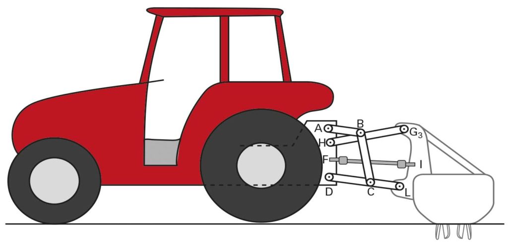
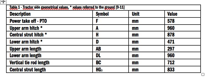
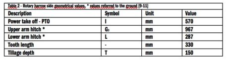
The last two parameters depend on the type of three-point hitch adopted for the equipment fixing to the tractor. For that reason, the evaluation of the operation angles of the cardan shaft has been deduced through experimental surveys of the necessary geometrical values referred to the examined machine. The figure 6 shows a lateral view of the tractor with the harrow in work position. The values reported in the Tables 1-2. refer to that figure.
The cardan shaft is composed by an input shaft fixed to the PTO of the tractor and by an output shaft coupled to the reducer of the rotary harrow. They are connected by an intermediate telescopic shaft and two universal joints. The adoption of the double universal joint, besides providing the tractor-harrow group with the possibility of facing mutual rotations, lifts and lowerings, allows a homokinetic transmission among the shafts that vary position in the space continuously. The figure 7 shows a scheme of the cardan shaft under examination [12-14].
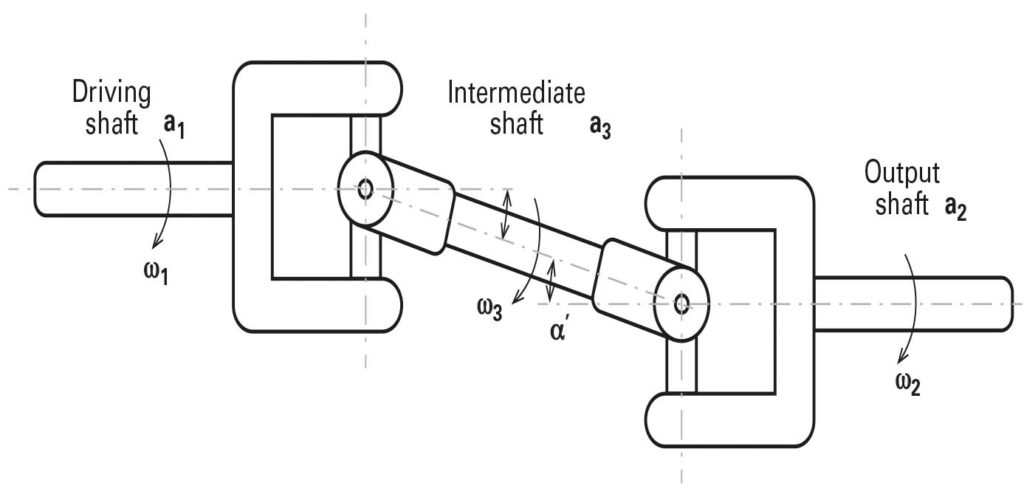
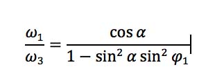
The ratio between the angular speeds of the driving shaft ω1 and of the intermediate shaft ω3 is:
Whereas the one between the angular speed of the driven shaft ω2 and the intermediate shaft is:
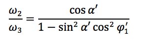
where is the angle between the normal to the plan of the axes of the connected shafts and the arm of the spider integral with the intermediate shaft, is the angle between the arm of the spider integral with the intermediate shaft and the plan of the intermediate and driven shaft, α and αʹ represent respectively the inclination angle between driving and driven shafts with the intermediate shaft [14].
In the study carried out, it was ascertained an alignment with error included between ± 1° [9] that is to say a transmission ratio close to the index unit of an optimal operation of the transmission between harrow and tractor.
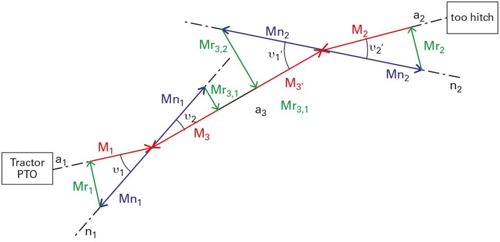
The main scheme of the cardan shaft under examination includes the three mentioned shafts (figure 8): input shaft (or driving shaft), intermediate shaft, output shaft (or driven shaft), respectively indicated as a1, a3, a2.
Referring to figure 8, we can notice that on the a1 shaft act the motor moment M1, the resistance spider moment Mn1 and the moment Mr1 due to the reaction of the support seen in correspondence of the PTO. On the intermediate shaft a3 there are instead the moments M3 and M3’, the moments Mn1 and Mn2 related to the two spiders and the reaction moments Mr3,1 and Mr3,2 due to the shaft constraints.
Finally, on the output shaft a2 we have the resistance moment M2, the moment Mn2 and the moment Mr2 due to the reaction of the support seen in correspondence of the operating machine.
In particular, the resistant moments at the spider (Mn1 and Mn2) have direction along the n straight line, perpendicular to the plan formed by the arms of the spiders while the reaction moments (Mr) are perpendicular to the respective shafts. In figure 8 are highlighted also directions and verses of the exchanged moments [12].
Besides, it has been created a parametric electronic sheet that allows analysing the transmission ratio and the moments present in the cardan shaft in various possible work configurations.
Reducer
The kinematic transmission chain, after the safety joint, provides for the speed reducer that transfers the motion to the rotors, as it is possible to observe in figure 3. Its presence has a double function: granting the variation between the rotation speed of rotors and the one of the PTO through an opportune transmission ratio; it allows the motion among incident rotation axes through conical torque.
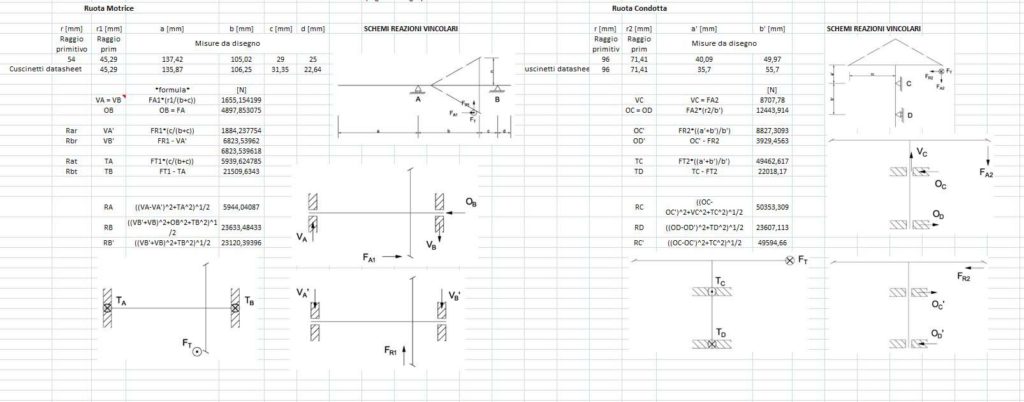
The creation of electronic parametric calculation sheets referred to the reducer allows: analysing the forces exchanged among toothed wheels; calculating the reactions on the supports of the shafts; checking shafts themselves at the variation of the harrow operating conditions. The figure 9 reports an example of electronic sheet for the calculation of the constraint reactions on some shafts of the reducer.
Gearbox
The harrow teeth, generally arranged vertically and in pair, are directly fixed to a series of toothed wheels that constitute the rotors of the harrow. They are positioned in a frame defined “gearbox”. The whole of the rotors is operated by the driving rotor (element 5 figure 3) connected with the reducer positioned upstream it and the meshes among the single rotors.
The tooth-ground interaction force generates a resistance torque that is included in the balance at the rotation of the single rotor together with the forces exchanged in mesh points. In this way, starting from the tooth-ground interaction, it is possible to evaluate the torque demanded to the shaft of the driving rotor or, considering the transmission ratio of the reducer, the one required to the PTO to carry out the ground tillage.
Conclusions
The article at stake illustrates the study of the kinematic chain present between the PTO of the tractor and the rotors of a rotary harrow, analysing all the components making it up and referring in particular to the mechanical actions that arouse in it during the ground tillage.
In particular, electronic parametric calculation sheets have been created for the evaluation of the actions exchanged among the organs of the entire transmission and for their sizing or for the assessment of the correct operation of the components of the kinematic chain under examination. They allow a fast analysis of the system also with rotary harrows characterized by different geometrical sizes, number of rotors, rotation speed of the PTO, transmission ratios and advancement speed of the tractor.
Currently, some FEM models are under construction to further study in-depth the tooth-ground interaction and to understand what parameters optimize the harrow performances and the ground finish obtained during the tillage. The results achieved until now are good and useful for the study of a rotary harrow under various operation conditions. www.polito.it
Acknowledgements
The present study is carried out in the ambit of the PRIN project: Research projects of relevant national interest – ban 2015 “Optimization of operating machines through the analysis of the mission profile for a more efficient agriculture” (duration 2017-2020). We thank the engineers. P.Annecchini, G. Conterno, N. Ferrero, N.Filippi, G.Foglia and the students A.Donati and G.Occhipinti for the support given in the study of the kinematic chain presented here.
[su_box title=”Bibliography” box_color=”#264a66″][1] G.Belforte, G.Eula, F.Racca, T.Raparelli, S.Sirolli, L.Comba, P.Gay, D.Ricauda, “Meccanismi di presa per la raccolta robotizzata di frutti e ortaggi”, Oleodinamica Pneumatica, ed. Tecniche Nuove, maggio 2015, pp.60-64; [2] G.Belforte, G.Eula, T.Raparelli, S.Sirolli, “Esempi di utilizzo della pneumatica in prototipi innovativi applicati in agricoltura”, Oleodinamica Pneumatica, ed. Tecniche Nuove, dicembre 2016, pp. 52-57; [3] T. Raparelli, G. Eula, A. Ivanov, G. Pepe, D.Ricauda Aimonino, “Preliminary analysis of interaction among gears, tines and soil in a rotary harrow”, International Journal of Mechanics and Control, ed. Levrotto e Bella (in progress). [4] “Studio della trasmissione meccanica di un erpice rotante per applicazioni in campo agricolo” Tesi di Laurea Triennale di Pierluigi Annecchini, Politecnico di Torino, Relatori: Prof. Terenziano Raparelli, Prof.ssa Gabriella Eula, Ottobre 2017. [5] ASAE Standards D497.4, Agricultural machinery management data. St. Joseph, Mich. Mar 1999. [6] Harrigan T.M., Rotz C.A. and Harrigan T., Draft relationships for tillage and seeding equipment. Applied engineering in agriculture, Vol. 11, No.6, pp.773-783, 1995. [7] Grisso R.D., Yasin M., Kocher M.F., Tillage implement forces operating in silty clay loam. ASAE Paper No. 94-1532, 1996. [8] Eurocardan http://www.eurocardan.net/ [9] “Analisi di un albero cardanico per applicazioni agricole tra trattrice ed erpice rotativo”, Tesi di Laurea Triennale di Gabriele Conterno, Politecnico di Torino, Relatori: Prof. Terenziano Raparelli, Prof.ssa Gabriella Eula, Prof. Alexandre Ivanov, Luglio 2018. [10] “Studio di un sollevatore a tre punti per trattrice agricola”, Tesi di Laurea Triennale di Vincenzo Castellana, Politecnico di Torino, Relatori: Prof. Terenziano Raparelli, Prof.ssa Gabriella Eula, Prof. Alexandre Ivanov, Marzo 2018. [11] “Analisi delle forze scambiate in un attacco a tre punti”, Tesi di Laurea Triennale di Nicolò Ferrero, Politecnico di Torino, Relatori: Prof. Terenziano Raparelli, Prof.ssa Gabriella Eula, Prof. Alexandre Ivanov, Luglio 2018. [12] Bongiovanni G., Roccati G., Giunti fissi, articolati, elastici e di sicurezza, Torino, LEVROTTO&BELLA, 1986. [13] Bongiovanni G., Roccati G., Giunti articolati, Torino, LEVROTTO&BELLA, 1984. [14] Belforte G.; Meccanica applicata alle macchine, Torino, LEVROTTO&BELLA, 2007.[/su_box]


