
This article presents the experimentation of a pneumatic control system to increase the stiffness of pneumostatic bearings.
Air bearings in general, and pneumatic ones in particular, allow precision motions since almost frictionless and therefore free from stick- slip. Thanks to these characteristics, due to the low viscosity of the air used as lubricant inside the meatus that separates the two surfaces in motion, such components are broadly used in supporting measuring machines. Their sizing is generally done to support a determinate external load and minimizing the necessary air consumption for the bearing feeding. Another important parameter that characterizes an air bearing is stiffness, that is to say the ratio between the variation of the external load and the consequent displacement on the bearing. The higher is stiffness, the higher is the precision with which the measuring machine operates.
Generally, it is possible to select a determinate bearing stiffness by choosing a suitable feed system with optimized feed hole diameters, since the relative pneumatic resistance, in series with the resistance of the air meatus, allows varying the downstream pressure of feeding holes following a load variation.
There are active and semi-active regulation systems that amplify the phenomenon of external load compensation, permitting, eventually, to obtain infinite stiffness. In general, semi-active systems use feedback mechanisms that exploit the same feeding pressure as the bearing. In active systems, the feedback is powered by a different source, generally electric.
In the article [1] we describe the different active systems used in literature. In the various solutions, we find orifices deformable by pressure [2] or flexible membranes whose deformation modifies the taper of the air meatus [3]. Systems of this kind permit to obtain very high stiffness on the bearing [4], even if in a limited operation range. The performances attainable with active systems are interesting for the reachable dynamic characteristics, the control structure is articulated and scarcely economic since it requires an adequate instrumentation outside the bearing. Semi-active solutions have not a high regulation speed (they are generally used in positioning systems where relatively long response times are admissible) but they are particularly interesting for the good static performances, cheapness and user friendliness.
At the Department of Mechanical and Aerospace Engineering of Turin Polytechnics are in course studies about bearings and the various control types. In [5] we show an active regulation system for pneumostatic bearings through electro-pneumatic valves controlled with PWM technique, in [6] we present a study of an active bearing controlled by piezoelectric actuators. They have recently engineered also a semi-active regulation system implemented with a pneumatic diaphragm regulation valve. The valve, of small sizes, is directly mounted on the bearing to be controlled, with clear advantage in terms of space taken up. In [7] we illustrate the design of such component, referring in particular to the numerical simulation that has allowed identifying the significant control parameters. The present article describes the experimentation carried out on the implemented valve prototype. The reported results, in terms of lift and air consumption, concern the static operation of the controlled bearing. Initially we present the test bench used, then we investigate the behaviour of the only bearing (considered passive in absence of control valve), finally we discuss the influence of control parameters on the behaviour of the active bearing.
The test bench
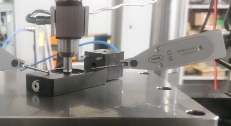
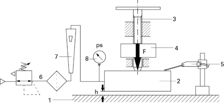
The static characteristics of lift and air consumption of the (passive and active) bearing are achieved with an opportune test bench that permits to measure the height of the air meatus generated under the bearing due to the application of a vertical load on the same. The scheme is described in figure 1, where are visible the bed (1), the bearing under test (2), the screw-nut screw system (3) for the load application, the load cell (4) for the force measurement and displacement sensors (5) for the detection of the air meatus height. Such sensors are positioned on the upper surface of the bearing and they detect its displacement following the opening of the pneumatic feed. Downstream the group (6), pressure regulator – filter, is present the flow meter (7) for the measurement of the consumed flow rate. The scheme shows the passive bearings, the ps feeding pressure at the inlet of the bearing is read on the pressure gauge (8). The filter allows an adequate filtering of the feeding air.
Scheme of the diaphragm valve
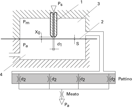
The scheme of the system valve plus bearing (active bearing) è visible in figure 2a. In this case the ps feeding pressure is supplied upstream the valve. The latter, screwed to the bearing, shows compactness features. It is constituted by a nozzle (1) with d1 calibrated diameter that faces the diaphragm (2). The diaphragm is a metal membrane with diameter of 6 mm and s calibrated thickness, which confers a certain stiffness to it. The membrane seals the control chamber (3) connected with the bearing inlet and realizes the variable resistance with the nozzle. The chamber (4) is placed as discharge (pa pressure). The nozzle can be positioned at different distances from the diaphragm through a system with screw and spring. Given x the distance between nozzle and diaphragm, x0 is the distance when pm is equal to the environment pressure (non- deformed membrane). The air, supplied to the ps pressure, crosses the nozzle axially and faces the membrane. In that zone we have a pressure drop caused by the channel narrowing, therefore the pm pressure in the control chamber (equal to the one upstream the bearing) is lower than ps. That value changes according to the operation point of the bearing.
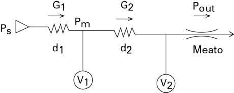
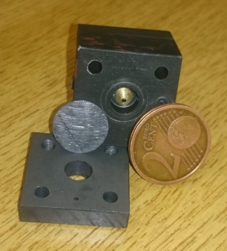
The pneumatic scheme of the regulation system is shown in figure 2b. G1 and G2 are the flow rates that cross the variable resistance of the valve and the input resistance of the bearing. Gout is the flow rate that crosses the bearing meatus. V1 and V2 are the volumes of the connection ducts of valve – bearing and of the meatus. The d1 diameter of the control valve nozzle must be compatible with the bearing consumptions (d2 diameter and number of feeding holes) to assure the due lift. The photo of figure 3 shows the implemented valve, the nozzle mounted in its inside and the metal membrane.
Operation of the regulation system
To highlight the advantage of the control system, the valve is fed at a ps pressure equal to the one used to feed the passive bearing. Initially we regulate the initial x distance to assure the nominal operation conditions, obtaining the required lift at the meatus height assigned to the bearing.
Due to a load variation applied to the bearing, we have a variation of the meatus height and of the pressure inside the control chamber of the valve. Due to the elasticity effect of the membrane, the latter warps until recovering a new balance condition. The numerical results show that, with opportune values of d1, s, x0 , it is possible to obtain an almost unvaried meatus height following the regulation.
The scheme in figure 2b shows that a first pressure drop is generated upstream the bearing owing to the air passage between nozzle and membrane, while a second pressure drop is due to the resistance of the inlet hole of the bearing. As highlighted in [7], to grant the lift requested to the controlled bearing, it is necessary to minimize the second pressure drop, entrusting only the variable resistance of the valve with the task of generating the useful pressure drop for the regulation. Therefore, unlike the passive bearing, the bearing with bigger feeding holes is more suitable for the control in case of semi – active static operation.
Experimental results
Passive bearing behaviour
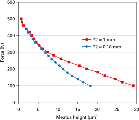
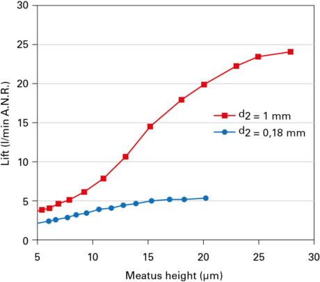
The first bearing used for the tests has rectangular shape, with 30 mm x 60 mm sizes. It is a commercial bearing, generally used for passive operation, equipped with four feeding holes with d2 diameter of 0.18 mm and a feeding system with a rectangular groove of opportune sizes to distribute better the feeding air in the meatus. The second tested bearing is similar to the first but it features feeding holes with d2 diameter equal to 1 mm to make it suitable for active operation.
The figure 4 shows the loading capacity (a) and the consumption (b) of the two bearings under passive operation conditions and at the ps feed pressure of 4 bars.
Active bearing behaviour
The control engineering, performed with the aid of a concentrated-parameter numerical model has allowed identifying the value of x0 to obtain the same loading capacity as the passive bearing (d2 = 0.18 mm) under nominal operation conditions (meatus 10 mm, loading capacity about 220 N).
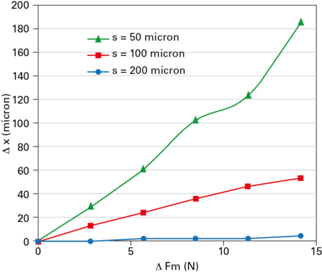
The static performance of the control were tested by using the bearing with d2 diameter holes equal to 1 mm. The results are obtained at the ps feed pressure of the valve equal to 4 bars. They implemented three interchangeable nozzles (d1=0.2, 0.5 and 1 mm) to adapt the valve also to bearings with different nominal consumption and lift as to the tested one. They provided for membranes of different thickness (50, 80 and 100 mm) to select the most opportune stiffness to the ends of the control. To measure experimentally the stiffness of the available membranes, they pressurized the control chamber by shutting the valve output. With the valve fixed to the bench, they measured the metal membrane deformation through a laser displacement transducer, placed at opportune distance.
The graph of figure 5 shows the Dx deformation according to the variation of the DFm pressure force exerted on the membrane.
The figure 6 shows the consumption of the open drain valve (pm = pa), depending on the x distance. The results refer to the nozzle diameters of 0.5 and 1 mm. The initial distance of the nozzle from the membrane is regulated by using the nozzle positioning screw. In order to vary the x distance with adequate precision, they decided pressurizing the chamber 4 (fig. 2a), normally operating as drain, with a known variable pressure. The membrane deformation was drawn from the measurement of the experimental stiffness of the membrane. The minimal flow rate values correspond to the situation of almost-contact between nozzle and membrane. The size of the valve nozzle hole must be the minimum needed to reproduce the nominal consumption of the passive bearing with d2 = 0.18 mm. Concerning the examined bearing, the most suitable d1 diameter for the control is the 1 mm-one.
Theoretical results indicate that the regulation is assured when the membrane displacement is at least of some dozen microns and that the static behaviour of the regulation system neatly improves as the metal membrane stiffness decreases. The initial nozzle positioning (x0) considers the deformation of the pressurized membrane: with a membrane thickness of 100 microns, the x0 distance is expected to be of some microns, while the membrane with 50-micron thickness would require the nozzle positioning under the non-deformed membrane profile (that is to say x0 with negative value). Actually, owing to the membrane deformability and the nozzle sizes, for the thinner membranes it is not possible to attain a spacing under 5 microns when they are under pressure. Besides, they assessed that km values under a certain threshold annul the control action. In fact, even if thinner membranes are more sensitive to the variations of pm pressure, with thicknesses inferior to 80 microns, emerge hysteresis phenomena that make the control instable. On the contrary, the membrane with 100-micron thickness is less deformed but the motion is repeatable, which makes it more suitable for the control. On the other hand, km values exceeding 300 N/mm frustrate again the control action owing to the almost non-deformability of the elastic element.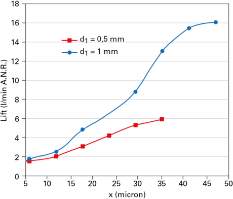
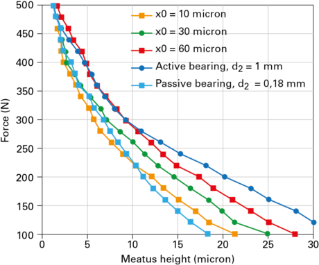
The figure 7 shows the experimental lift of the active bearing (d2 = 1 mm) with membrane of 100 micron thickness, for some set values of x0 (10, 30, 60 microns) and with d1 = 1 mm. The curves position among the curves of the passive bearing previously discussed (d2 = 1 mm and d2 = 0.18 mm); in particular, the lift increases with the rise of x0, while the bearing stiffness grows as x0 diminishes. The minimum set x0 distance (10 microns) makes the lift and the stiffness of the bearing (at 12 microns of meatus) respectively (slightly) higher or lower than the passive bearing one. Therefore, it is necessary to further improve the control system to obtain relevant increases of bearing stiffness, as demonstrated by the numerical simulation, too. In spite of that, it is worth noticing that the stiffness of the active bearing, even with nozzles of 1 mm-diameter, is similar to that of the passive bearing, which features nozzles with minor diameter (0.18 mm). Therefore, the valve presence creates the inner compensation effect generally introduced by calibrated nozzles.
To make the control action effective, it is necessary to obtain a higher membrane deformability but avoiding reducing the thickness excessively. It is possible to obtain a significant improvement of the bearing stiffness using an alternative solution as to that making use of a metal membrane. The metal membrane has been replaced by a membrane of rubberized canvas in contact with the helical spring of opportune stiffness, mounted on the chamber facing the control one with a light preload. Even if the membrane mobility is increased, the motion turned out to be still scarcely repeatable, consequently limiting the control performances. Further investigations with alternative solutions are in course to solve the problem.
Conclusions
They have implemented a pneumatic control system to increase the stiffness of pneumostatic bearings. The system, interesting for the user friendliness and the implementation cheapness, uses a diaphragm control valve. Experimental tests, concerning the static performances of the control, are aimed at choosing the sizes of the valve nozzle diameter, diaphragm thickness and the regulation of the distance between nozzle and diaphragm. The attained results show how the solution with diaphragm is preferable as far as the behaviour repeatability is concerned, however the diaphragm deformability must be further increased. Today are in course new investigations concerning the typology and the sizes of the diaphragm to be used, in order to improve the valve performances to further increase the active bearing stiffness and make it higher than the passive bearing one, even maintaining the same loading capacity.
Federico Colombo, Danial Ghodsiyeh, Terenziano Raparelli, Andrea Trivella, Vladimir Viktorov, DIMEAS, Politecnico di Torino, www.polito.it


