
Federico Colombo, Terenziano Raparelli
Politecnico di Torino –
In the ambit of the CARI regional project, the Politecnico di Torino is developing a turbocompressor to feed a fuel cell system for vehicle applications, needing compactness and lightness for an optimal operation. To pursue that goal it is necessary to increase the rotation speed to manage, with reduced overall dimensions, the same quantity of air with equal compression ratio. To that end, it is necessary to redesign the geometry of the compressor rotor completely, by means of CFD instruments, and to redesign the complete system of bearings, motor and cooling system.
Recently the combination of several factors, including the progressive depletion of fossil fuels, the air pollution and the increase of the energy demand, has favoured the development, still in course, of new technologies that use alternative sources of energy, like for instance solar, geothermal and hydrogen. Concerning the latter, fuel cell systems are considered one of the most promising alternatives to fossil fuels, both for the efficiencies obtained and for the environmental compatibility. In automotive field, hydrogen cells are deemed an eco-friendly drive system since it produces just water, deriving from the reaction between hydrogen and oxygen. The cell feeds the electrical motor and therefore allows exploiting hydrogen fully as green energy vector.
For an optimal operation of a hydrogen cell or fuel cell it is necessary to bring an air flow at constant pressure to the cathode by means of a compact and light compressor. The air flow must be instead variable depending on the power demanded by the electrical motor. The compressors used for that purpose are, in the majority of cases, purposely developed turbocompressors, since they need reduced weights and overall dimensions to be used in mobile applications. High-speed technologies are exploited to satisfy those requirements. Apart from this, however, it is necessary to solve various problems, among which the main ones are the heating of components and the service life of bearings. The higher heating is due both to frictions and to the motor that must manage the same power in smaller spaces. This results in a much higher power density than the standard one.
In this article we are showing a prototyping system of the compressed air management for fuel cells in vehicle ambit. The system, developed by the LAQ-IBIS laboratory of the Politecnico di Torino with the collaboration of other research and industrial partners, is supported by oil free bearings and supplies contaminant-free compressed air to the stacks of the PEM cell. The air compressor is rotated by an electrical motor and is supported by high-speed air bearings. In the specific case, the laboratory activities concern air bearings. The professors Belforte, Raparelli and Viktorov and the engineers Colombo, Trivella and Villavicencio take part in the activities.
Fuel cell architecture for mobile applications
The most renowned fuel cell, from its English denomination, is the proton exchange membrane type, or PEM. This typology is characterized by a fast response to energy requests and it is therefore very suitable for mobile applications, in particular in vehicles. The hydrogen is split into protons and electrons on the anode; protons cross the membrane to reach the cathode, where they react with the oxygen contained in the air.
The electrons pass instead through the external circuit to reach the cathode and to recombine, thus supplying electrical power. The hydrogen cell plant needs some auxiliary systems to manage the flows of air and hydrogen, for the thermal regulation, the wetness control and for the electrical power conditioning, since the motor on-board generally operates with alternate current.
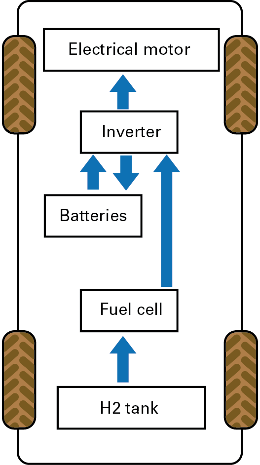
A fuel cell vehicle exclusively uses electrical energy to move the means. This is produced in the fuel cell starting from the energy accumulated in the hydrogen tank.
The figure 1 shows the basic scheme of the vehicle.
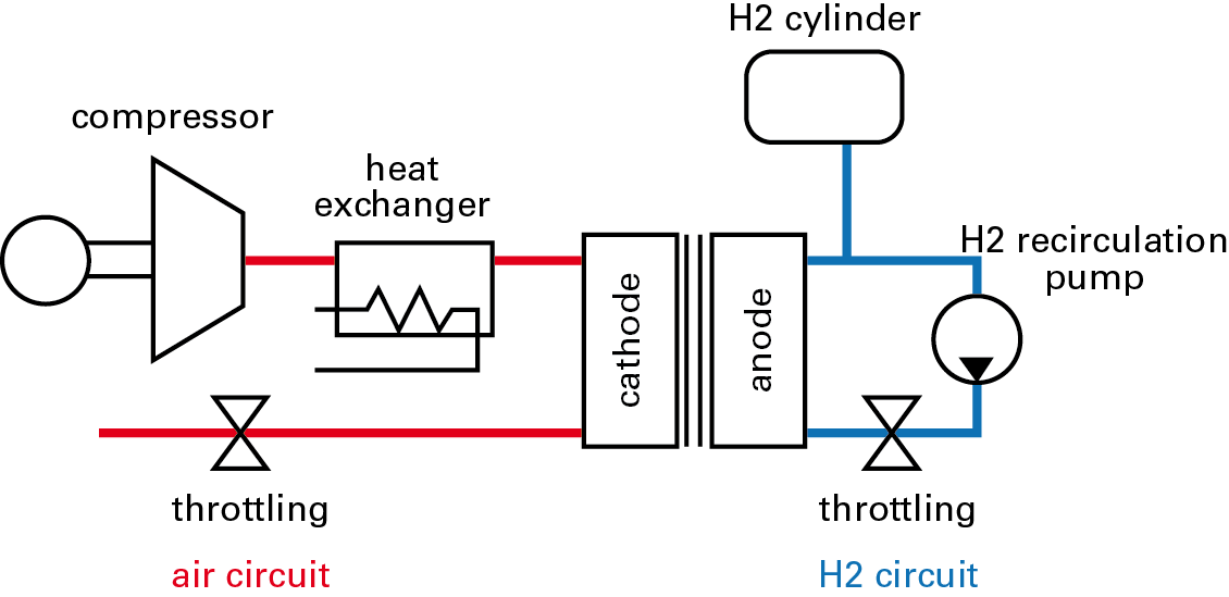
The energy is stored in the tank under the form of liquid or gaseous hydrogen. In the first case the pressure is of 700 bars, in the second it decreases to 300 bars, as well as the complexity and the weight of the tank. The inverter supplies the motor with the necessary power and keeps batteries charged. The air and hydrogen management systems are equipped with purposely developed compressors, which must be very compact and light. The figure 2 shows the scheme of the fuel cell with the auxiliary systems for the management of air and hydrogen flows.
The compressor
In the present paragraph we are describing the prototype of the oil free compressor that has been developed. The figure 3 shows a scheme, where we can see the asynchronous motor (1) that accelerates up to 70000 rpm, the shaft (2) on which is mounted the rotor (3) of the compressor.
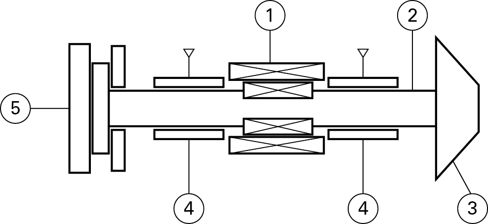
The motor needs no speed sensors for its operation. The controller feeds the variable frequency motor by enabling its regulation from zero up to the highest speed. The temperature of the motor and of the bearings is kept under control by a liquid cooling system with closed circuit. Radial bearings (4) are of air type, externally pressurized. They have been designed to grant stability up to the highest rotation speed. The axial thrust bearing (5) is instead of dynamic type and provides a loading capacity that increases hand in hand with the rotation speed. It is a self-sustaining bearing that therefore does not need any external power supply.
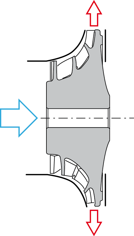
In the section of figure 4 the mixed type rotor is visible, with the axial air input and the radial output.
Dimensioning of radial bearings
Some geometries of radial bearings have been considered, by varying the following parameters: the diameter and the axial length of bearings, the number of feeding nozzles and the air layer existing between rotor and bearings. Each different geometrical configuration has been simulated under static conditions for the stiffness calculation and under dynamic conditions for the stability testing. They have calculated the pressure distribution inside bearings by means of opportune simulation software and they have drawn the shaft trajectories performed at the different rotation speeds.
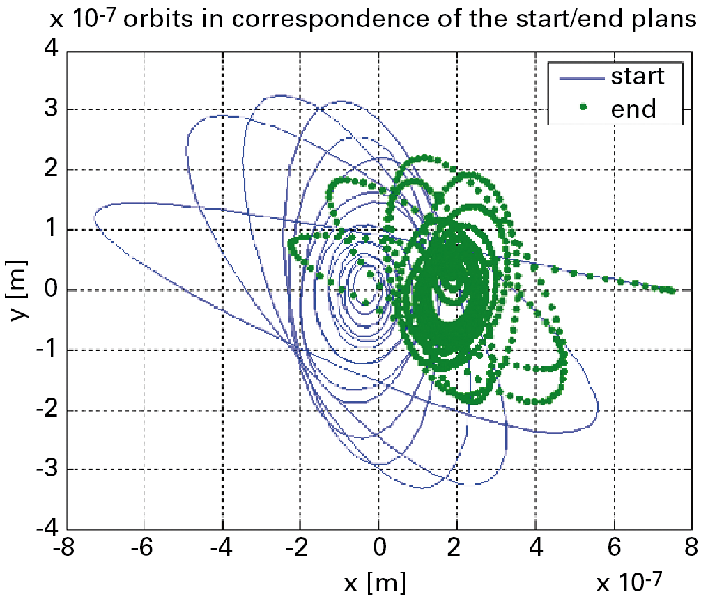
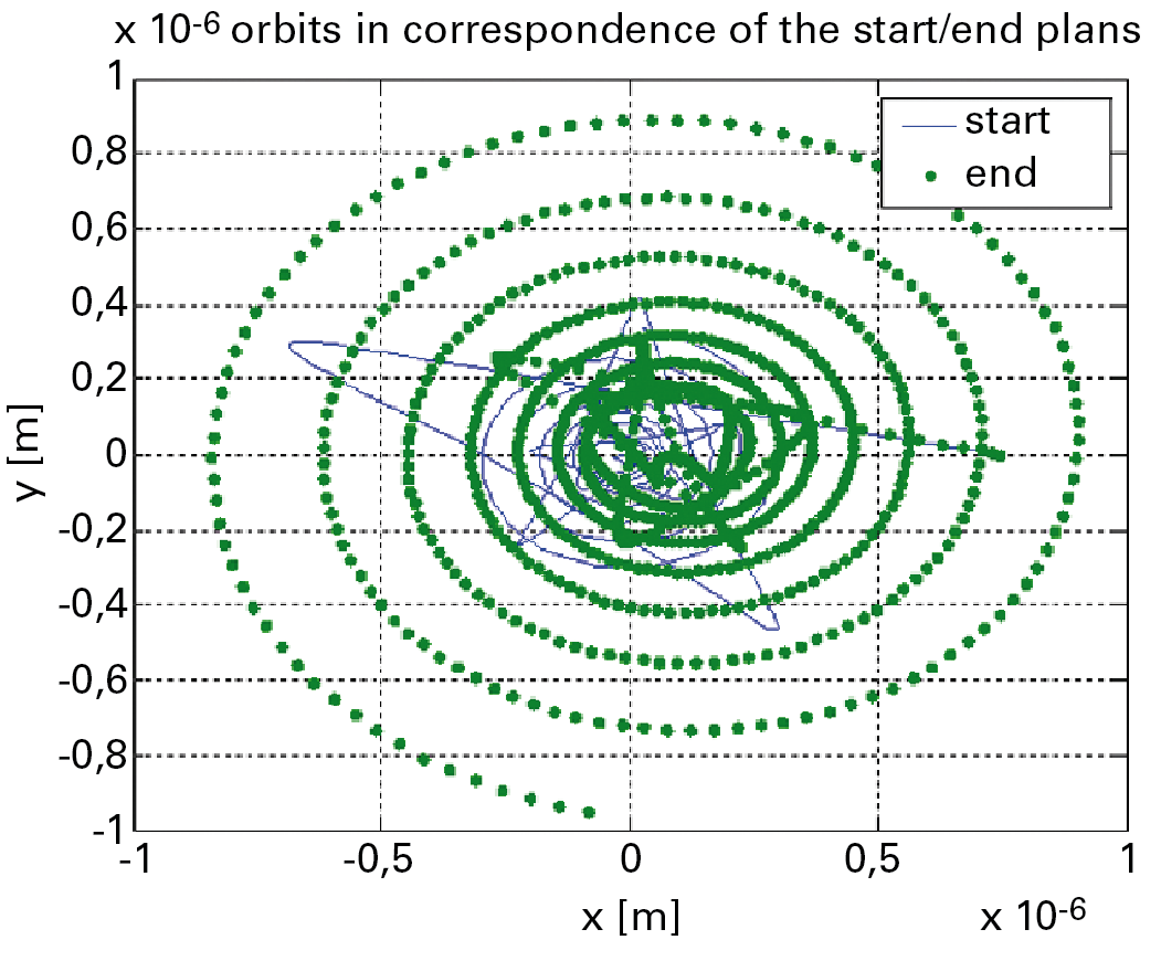
The figures 5 and 6 show the comparison between the rotor trajectories in a stable and in an instable case. They are represented the trajectories that the rotor, assumed to be rigid, travels inside the bearings in correspondence of two radial plans positioned at the extremities of the bearings. In the first case bearings cannot bear the centrifugal forces of the rotor since they act with a certain delay in comparison with them.
This results in an increase of the orbit of the rotor, which stops only with the contact between rotor and bearings. Obviously, a situation of this kind must be avoided because it determines the damaging of the parts that come into contact one another. The second case is on the contrary a stable case because the orbit radius decreases. Simulations of this type allow testing the stability of the rotor-bearings system. A good design of bearings cannot set these verifications aside.
Further details
Besides the simulations concerning the dynamics of rotor and bearings, they have developed some considerations about thermal aspects and the effect of centrifugal forces due to the high speed.
They have evaluated the static and dynamic performances, overall dimensions and weight of the compressor. If compared with dynamic compressors with equal compression ratio and managed air flow rate, the developed prototype is more compact and operates at higher rotation speeds. In order to reduce the rotor sizes, a scale reduction starting from known geometries was not enough but it was necessary to carry out a detail fluido-dynamic analysis of the rotor pipes through CFD instruments.
The detail design has been accomplished and the compressor is under implementation: the parts have been finished and are ready for the final assembly.
They plan in the future to connect the compressor with a fuel cell to verify not only its operation in itself, but also of the complete system.
An analogue compressor of the type with side channels has been developed for the hydrogen recirculation. In this case rolling bearings have been provided since the rotation speed is relatively low (15,000 rpm).
Conclusions
In conclusion, a turbocompressor with mixed-type rotor has been developed (axial input and radial output). They have developed oil-free high-speed radial bearings and in particular a self-sustaining axial thrust bearing. The system is particularly compact if compared with other compressors with equal air flow rate managed.


