
Carlo Molon
Agent of VEST Inc., Troy, MI (USA) –
By automating all the repetitive tasks and removing errors, MDTools gives to the designer a set of features for a fast, safe, fun and productive hydraulic Manifold block design process.
The design of hydraulic Manifold blocks requires both, a considerable attention to detail and to ability. Attention to detail as defined for example by the correct connection between ports to match the original circuit, and an attention to ability as in the ability to pre- view the result, optimize size by choosing the best cavity position, reducing construction ports, etc.
The 3D modeling of the block also provides an attention to:
– minimum wall thickness, to avoid resistance problems;
– manifold manufacturability, to avoid unnecessary machining;
– correct circuit, which seems obvious, but is far from trivial to check a block with a few dozen valves;
– quality of the connections, with a focus on drilling depth;
– oil flow rate, to properly size the connection holes and reduce the pressure drop in the circuit.
While, the design was done with AutoCAD 2D in the years past, now almost exclusively, it is done in parametric 3D CAD environments. The market offers different CAD solutions. They are all so versatile that none of them is optimized for the hydraulic Manifold design.
Design a hydraulic manifold in half the time
In the computer industry we speak about ‘horizontal’ software and ‘vertical’ software: the former is generic, good for everything, the latter is specific, perfect for a particular job.
MDTools of Vest Inc is a ‘vertical’ software to design hydraulic Manifolds. Designing blocks with the help of MDTools is a completely different experience from using a generic 3D CAD software. The savings in terms of time is significant ( never less than 50%, and often as much as 70%), with the further advantage of minimizing design errors and therefore hidden costs due to wrong prototypes (loss of time in production, testing, etc.).
MDTools integrates seamlessly with Autodesk Inventor or Solidworks. If you design hydraulic blocks with either of these systems you must try MDTools,And if, on the other hand, you use a different CAD system MDTools could convince you to change it!
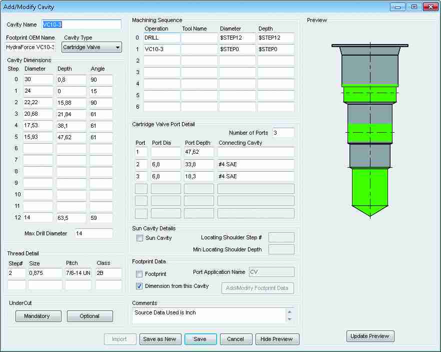
MDTools comes with a library of hundreds of cavities of the largest fluid power manufacturers, all cavities geometrically defined and ready to use. And,thanks to a graphical user interface, adding a new one is easy,.
Each cavity comes with its machining information. Every time you insert a cavity from your library you are already creating your machining drawing.
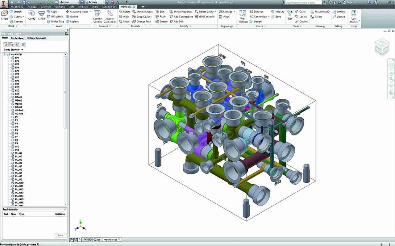
Cavity insertion in the 3D model comes via a menu integrated into the browser. Each cavity has colored surfaces corresponding to the working area. Each net will have a different color [ this is common practice for a manifold designer to check the circuit.] With MDTools all the colors are created automatically. MDTools will alert you if you try to connect cavities belonging to different nets. MDTools will check net integrity and will raise an alert if you miss something and/or if you do something wrong. This implies that the circuit cannot be incorrect , unless of course the designer is committed to making mistakes! You also don’t need to produce a prototype to realize that the circuit is wrong!
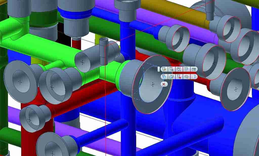
In the part model environment the designer finds all the commands needed to quickly design the block i.e. move or change cavity face, swap two cavities, copy one or more cavities, add engraving texts, add additional holes, counterbores, offset holes, undercuts, o-ring grooves, slots, etc. . With everything available at your fingertips, after selecting the cavity you want to modify, the main controls are accessible through a flyout menu for an efficient design.
When designers add construction ports, they need to remember cavity geometry to insert a correct diameter (if the diameter is too big it could create problems with the assembly and valves operation). At the same time they should always keep in mind oil flow rate, to pay attention to oil velocities inside the manifold. MDTools takes care of both aspects and when possible it will suggest an appropriate diameter for oil velocity. If the geometry is too strict, MDTools will guide the drill selection. In addition, MDTools will optimize drill depth to reduce pressure drops in the manifold.
With MDTools and at anytime during the design process, you can check minimum wall thickness for all the block, for a set of cavities or between specified cavities. You can also check for the quality of connections and for the wrong or missing connections.
Drill depth optimization is automatic for the block and is related to an energy efficiency study VEST runs on the Manifolds block.MDTools allows the designer to take an overall look at velocities in the Manifold to help make sure there are no critical situations.
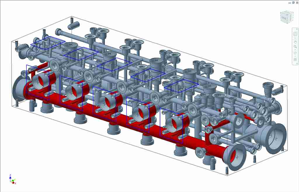
Several of the following commands allow the designer to graphically check the Manifold. These are, hide cavities, display cavity names in the Manifold, remove colors or show one or more net. A free viewer can be installed in any computer without the need for MDTools, that lets the viewer take a look inside the Manifold to graphically check cavities, nets, drill intersections. This feature could be very useful for Manifold production. Imagine if you could deliver to a manufacturing department a machining drawing together with a smart 3D model designed to show them what is inside a Manifold.
3D assembly
MDTools can read if a cavity is a drill hole, a cartridge cavity, a footprint, a construction port, etc. With just one command MDTools could plug all construction ports. Imagine then a large manifold with many (20? 50? 100?) construction ports. The increase in time saving would be exponential.
For tasks related to cartridge valves or surface mounted valves, you can manually link a 3D model to its cavity and MDTools will assemble them without the need to add constraints each time.
If you start from a circuit drawn with HyDraw, circuit drawing software developed by VEST, the assembly can be fully automatic. In just a few seconds and no matter what the complexity you could have your assembly ready.
From 3D model to machining drawing, without errors
When designers create a machining drawing, the manual process can be dangerous as it is essentially a repetitive task. An error in the machining drawing could lead to a wrong Manifold in production and that could cost lot of money.
If you can design a safe 3D manifold block in part environment, there’s no reason to create an error with the machining drawing. That’s why MDTools can fully automate a machining drawing. One command and in a few minutes your machining is created by reading the pre-checked 3D geometry.
Whether you use machining callouts or a bore chart, both options are available and, if you need to, you can export the machining chart to an external file.
MDTools is a professional tool to help design hydraulic Manifolds in a 3D environment and has been developed by VEST Inc.


hi dear sir.
I am hydraulic man and design the hydraulic blocks in catia that is most time expensive and a little hard. by search i know that the mdtools essential is very strong software for designing the hydraulic blocks. would you oblige me to send me free source of this program?
Dear Eng. Aboutalebi,
I thank you for appreciating the content of our magazine Power Transmission World.
For any request about MDTools, you could contact Vesta Automation, Italian Branch, Mr. Ghedin, http://www.vestusa.com
Best regards
Anna Bonanomi