
Guido Belforte, Federico Colombo, Terenziano Raparelli, Andrea Trivella, Vladimir Viktorov –
In the high speed field, pneumatic supports have an essential role. They are used not only in research prototypes, but also in high speed commercial electrospindles and other applications.
Air supports are used in those applications where it is necessary to obtain high precision or high rotation speeds. In the latter case, thanks to the low air viscosity, the air bearings allow the support of rotating organs up to rotation speeds which are impossible for rolling bearings.
To give an idea of numbers, on the market there are electrospindles for the drilling of pre-printed cards which go over 200,000 turns/min.
The item is a prototype of a totally pneumatic electrospindle, designed in the Mechanical and Aerospace Department of the Politecnico of Turin, and is different because of the presence of air supports instead of rolling supports. Two radial bearings with an axial length of 100 mm, support the mandrel which has a diameter of 50 mm. Also the axial thrust bearing is pneumatic and made up of two disks which lead the swivel ring of the mandrel thanks to the air input of compressed air in the interposed meatus (clearance).
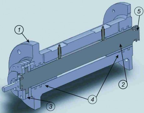
The section of figure 1 shows the functioning of the bearings. The external carter (1) is equipped with a series of axial and radial channels which distribute compressed air on the axial (3) and radial bearings (4). The compressed air, arriving almost to the bearings, crosses a series of calibrated holes and goes into the meatus (clearance) which is interposed between the mandrel (2) and the carter. The pressure distribution created in the meatus (clearance), allows a carrying capacity able to support the mandrel even if there are external forces. An air turbine (5) can be used as an alternative to an electrical engine to adjust the speed of the mandrel. On the opposite extremity a nose is mounted where it is possible to apply some forces during the rotation. This nose is useful during an experimental research phase in order to measure the stiffness of the bearings. A series of moving sensors are inserted in the carter in radial position and make it possible to detect the eccentricity created between mandrel and bearings when there is an external force applied to the mandrel. These sensors not only make it possible to detect the rigidity of the bearings, but also the vibrations of the mandrel during the rotation.
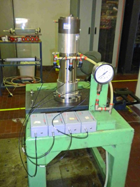
The electrospindle (fig. 2) is equipped with an electrical engine of 75,000 turns/min and power of 2,5 kW. The tests carried out in the Department have verified the functioning during the cutting process. In place of the spindle nose a plier for machine tools was mounted and the cutting tests were performed with HSS and HSC slot cutters with diameters from 1 to 6 mm processing a resin. Through a motorized guide, different speeds of advancement towards the material to be processed were set.
To measure the cutting strengths, a plate equipped with piezoelectric transgressed load cells was mounted on a cross slide guide with controlled speed, with which it is possible to measure the force applied to the plate along the three directions X, Y and Z.
The underlying cross slide guide is connected, by a screw-internal screw thread system, to a stepper motor with a programmable speed. The system is mounted on a platform which has a regulating height which allows a manual approach to the slot cutter of the mandrel.
In case of peripheral milling, the stiffness of the bearings should be as high as possible in order to minimize the failure of the tool after the application of a cutting force, and to make the processing mistakes negligible. So, in order to obtain the required stiffness, it is essential to dimension the bearings.
In case of air bearings, there are different factors that influence this parameter: first of all the supply pressure and the entity of the air meatus (clearance), but also the number, position and diameter of the calibrated supply holes. With a 6 bar supply, the measured stiffness in correspondence of the nose, is of about 50 N/micron.
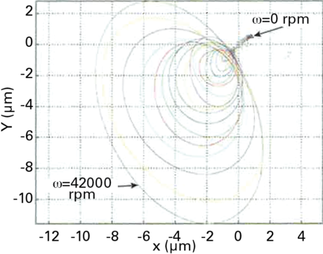
- Fig. 3 – Orbits measured at different rotation speeds.
To check the spindle vibrations especially at high speed, it is appropriate to register the orbits made by it around the center of the bearings. Picture 3 shows an example of orbits measured at different speeds, from 0 to 42.000 turns/min. These orbits are obtained by composing the signals of the sensors located along the X and Y axes.
The functioning is stable, even if the width of the orbit is not negligible due to the residual imbalances.
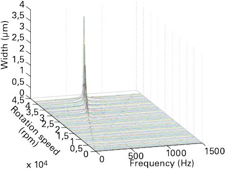
The stability can be checked both on the time diagrams, in case the width of the vibration does not increase, and on the spectrum in the frequency of the signal, which must have a single contribution in frequency which is synchronous with the rotating speed of the mandrel.
In fact, in case of a second frequency, typically equal to half of the synchronous frequency, the bearing would start losing stability and if the supply pressure should decrease or the rotation speed should increase, the mandrel would seize up.
In case of well-designed bearings, it is possible to avoid this situation. In the “waterfall diagram of frequencies” (fig. 4), only the synchronous frequency contribution appears, therefore there are no risks of damaging the prototype.
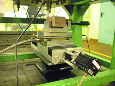
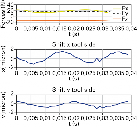
In figure 5 the system during the measurement of the cutting forces is visible. The results shown in figure 6 show the time diagrams of the cutting force and of the subsequent movement of the mandrel in respect to the center of the bearings.
Conclusions
It is possible to design high speed mandrels (over 30.000 turns/min) of significant dimensions (diameter of 50 mm), characterized by high values of axial and radial stiffness, suitable to implement peripheral milling.
These objectives can be achieved using the pneumatic technology and developing air bearings of an appropriate geometry, able to support the mandrel up to a rotation speed not compatible with rotating bearings and to develop the load capacities and required rigidities.


