
Andrea Manuello Bertetto
Department of Mechanical, Chemicals and Materials Engineering
Università degli Studi di Cagliari, Italy –
Vacuum can be defined as the absence of matter in a given volume; it is a limit concept of physics. For many applications vacuum represents an ideal working environment, sometimes indispensable. In conclusion, it is necessary to produce vacuum through appropriate processes.
In industry vacuum generation is created with different systems depending on the required degree of vacuum and fluid flow. Figure 1 shows some types of pumps for vacuum generation. Figure 1a shows a membrane vacuum pump capable of reaching high degrees of vacuum and treat medium flows. In the chamber (1) the fluid is sucked through the membrane piston (2), dragged by a crank-connecting rod system. An automatic valve (3) allows fluid access in the chamber; after the fluid is expelled through a second automatic valve (4). Figure 1b shows the outline of a peristaltic pump which discharges from its mouth (1) after sucking from it (2), creating a vacuum. This pump is volumetric and has as reference the volume determined by the part of deformable pipe (3) which is squeezed between the planetary rollers (4), moved from the gear train (5) and the track on the stator (6) of the pump. The gear train is dragged by an engine.
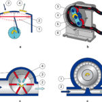
The vacuum level achievable with this device is high, also because of the elasticity of the deformable pipe. Figure 1 c shows the outline of a vane pump for vacuum generation that draws from (1) and sends to (2). It has an impeller (3) mounted in eccentric position with vanes (4) that can flow within the impeller. The vanes are kept in contact with the stator’s sides; each chamber is defined by two successive vanes and by impeller and stator. When the impeller rotates, the centrifugal force pushes the vanes outwards. The eccentric position of the impeller forms chambers (5), with variable volume with the rotation of the impeller, causing pressure decrease in vacuum environment. The outline of vacuum blowers, which exploit the change in fluid motion, is shown in figure 1d. They have high capacity, but do not reach a high vacuum level. Through the rotary movement of the vanes (1), the air undergoes acceleration. The action of the vanes, which involve air, produces vacuum on the suction side (2). The exhaust air is then discharged (3).
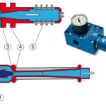
Besides using vacuum pumps or blowing pumps, also ejectors can be used to generate vacuum: they produce vacuum by exploiting the properties of Venturi tube. An outline of an ejector and one of its sections is shown in figure 2: compressed air is injected in the ejector (1) and sucked from the mouth (2), because of dragging effect created with the nozzle (3). Immediately after the nozzle, in the area (4) vacuum is created and the air is sucked in through the mouth (2), from where you want to generate the vacuum. Compressed air and sucked air go out through the silencer (5). Often compact, single stage ejectors are used, with suction valves and exhaust valves to control directly gripping or expulsion of the workpiece and with vacuum switch for control and regulation of the system.
There are also multi-stage ejectors with greater suction capacity than single-stage ejectors, but they are bulkier and requiring non-return valves, which compromises security that is typical of purely fluidic elements.
A particularly interesting ejector is the one whose outline is shown in figure 3. This type of ejector exploits a particular phenomenon, relative to the viscosity of fluids, called Coanda effect: Coanda effect was discovered in 1950 by Romanian aeronautical engineer Henri Coanda (1885-1972); he noted that a fluid tends to follow the contour of the surface on which it weighs on, if the curve of the surface and the flow angle of incidence in relation to the surface, are not too accentuated.
In figure 3 you can see that the feeding air comes inside the ejector from its mouth (1) and enters the nozzle area through an annular passage (2). The flow adheres to the wall and starts going toward the divergent, dragging the flow from the intake area (3), where it causes pressure decrease. In (4), both feeding and sucked flow are exhausted.
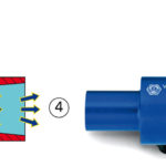
Injectors are often mounted directly on vacuum grippers. In figure 4 there is a suction cup directly mounted on a single-stage ejector, equipped with a device for rapid detachment.
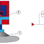
The suction cup (1) is subject to the vacuum generated by the ejector (2) fed by the mouth (3) which also feeds the chamber (4), maintained under pressure until the ejector is operating and isolated from the suction cup through a disk shutter (5), with lip seal, which allows the load of the chamber. When the power of the ejector is stopped, the pressure in the chamber acts from the inside of the lip by picking up the disc shutter and causing pressurization of the suction cup, resulting in the rapid expulsion of the piece.
Vacuum for robotic handling
The force generated by the vacuum along the axis of a suction cup will be the product of environment pressure drop multiplied by the area of the suction cup, projected along the axis of the suction cup. The components that are perpendicular to the axis of the suction cup will be balanced by the actions of friction between suction cup and workpiece.
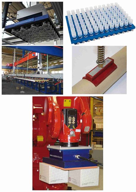
In the opening figure are shown some applications of vacuum technique for parallel gripping of delicate objects: there is a vacuum system for parallel gripping of delicate objects consisting of cylindrical glass elements, this can be done with high efficiency using gripping surfaces with suction cups with self-closing valves of the type shown in the same figure: Vuototecnica’s Octopus systems. Moreover, in the same figure is shown the gripping phase of large sheets and gripping of cylindrical objects. Finally, in the last figure, a system of gripping surfaces which allows gripping of boxes, handled by a robot (the wrist can be seen).
Conclusions
Vacuum is able to meet the most diverse needs in scientific and industrial field, with interesting responses for gripping and handling.
Thanks
The author would like to thank the Italian company Vuototecnica from Beverate di Brivio near Lecco, for information and images kindly made available.
Bibliography
K. Diels and R. Jaeckel, Leybold vacuum handbook Oxford: Pergamon, 1966.
G. Belforte, Manuale di Pneumatica, Tecniche Nuove, Milano, 2005.
Guthrie, Vacuum Technology, John Wiley & Sons, 1963.


