
When speaking of quantification of the efficiency of a system, we mean the calculation of its thermodynamic efficiency, defined as the mathematical ratio between the input energy, i.e. the energy entering the considered system (in any of its forms: electric, chemical, thermal …), and the output energy (once more, in any of its forms), expressed with a pure number (between 0 and 1) or as percentage. The quantification of the efficiency is not a simple operation because it implies a very precise control of the energy flows that cross the boundary of the analysed system, but it is always useful as it is associated to the goodness of the energy transformations that occur inside that system.
The operation of calculation of a system’s efficiency has another very interesting implication, which concerns the quantification of the portion of input energy that is dissipated inside the system as heat, and, hence, which is cause of structural expansions and possible overheating affecting also adjacent systems.
Marco Bietresato, Franco Concli, Fabrizio Mazzetto
Free University of Bolzano, Faculty of Science and Technology
Systems for measuring the global efficiency of the motor in agricultural machines
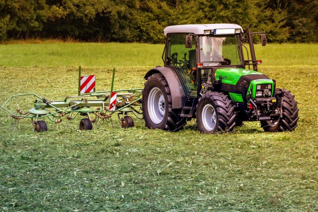
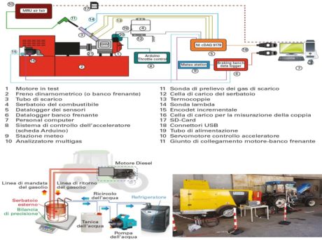
An agricultural machine, as any other vehicle, is a technical system with a high complexity, further increased, compared to cars, by the presence of a series of mechanical and hydraulic interfaces (or “power take-offs”) for the operation of agricultural implements. Focussing on tractors and schematizing their powertrain system as a set of energy-generating, energy-transmitting and energy-utilizing components, we can therefore notice that, against a single energy-generating subsystem (the motor), there are many utilizers, differently positioned in the path followed by the power to reach the wheels (which is the utilizer most “far” from the motor; Figure 1).
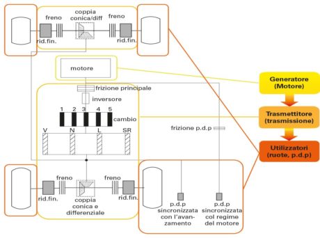
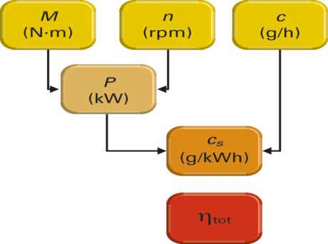
The mechanical power-take-off (“PTO”) is configured like a splined shaft with standardized splines; a cardan shaft can be connected to the PTO to drive any agricultural implement. In its simplest version (PTO synchronized with the engine speed), the connection with the motor is almost direct and does not involve the gearbox, therefore it is possible to use the mechanical power take-off to connect a dynamometric brake with the tractor motor thus plotting its characteristic curves (torque and power at full throttle). The dynamometric brake (or dyno) is a device (generally hydraulic or electric) that applies a braking torque to the splined shaft of the tractor mechanical PTO, meanwhile detecting its rotational speed. It can detect the motor torque value in its entire speed range by measuring the applied breaking torque as the motor speed decreases, according to the Newton’s third law of motion. However, the motor efficiency cannot be calculated from this quantity only (Figure 2): it is necessary to use an instantaneous consumption meter device (inserted in series in the fuelling line) or a chronogravimetric system (which measures the decrement of fuel mass in a tank over the time; Figure 3) to obtain the fuel consumption values (expressed in g h-1). The fuel (mass) specific consumption cs at the different engine speeds is attained by dividing the fuel consumption values by the power values delivered by the motor (measured at the dyno, in kW); it allows the calculation of the engine global efficiency η (%), given the lower heating value (LHV) of the used fuel (for diesel oil it is 42400 kJ kg-1):
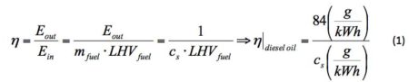
where η – engine global efficiency, %;
Ein – energy entering the machine, J;
Eout – energy going out of the machine, J;
mfuel – fuel mass, kg;
LHVfuel – lower heating value of the fuel, kJ kg-1;
cs – specific fuel consumption, g (kWh)-1.
Measurement of the efficiency of the transmissions used in agricultural machines
The task of a transmission is adapting the operative conditions of the motor to the user’s demands, in terms of rotational speed and transmitted torque. The adaptation of these quantities is operated in the time domain of the motor and the user, therefore in the time phases of: start, transient/steady state, stop (of the supply/demand for power). In the case of electric motors, which have a very extended speed-range and a non-null torque also with motionless rotor, the motor can directly suit the user’s requests, therefore the transmission system is simplified and includes only the transmission shaft. Vice versa, when the power source is a thermal motor, the complexity of transmission systems increases notably and the many vehicle manufacturers have developed even very refined engineering solutions: automated mechanical transmissions with hydrokinetic coupling (torque converter), mechanical transmissions with fixed gear-ratios and two clutches, continuous variable hydraulic-mechanical transmissions (CVT).
Mechanical transmissions play a fundamental role especially in agricultural machines, characterized by the need of not interrupting the torque at the wheels while shifting the gears; one of the latest innovations in the automotive field (i.e., the dual-clutch gearboxes, in agriculture indicated as multiple electro-actuated clutches or full-powershift gearboxes) is actually derived from the solutions initially studied for the agricultural machines. The crop operations that can be carried out by a tractor are many, and each of them is characterized by an optimal interval of the vehicle speed and especially by a different need for torque and power; for example, we should just consider the operations of ploughing (where there is an important interaction of the implement with the soil), of plant-protection products distribution (in which there is the haulage of an implement-trailer and, simultaneously, the operation of a pump and a fan) or of hay raking (with which the hay is collected in windrows). In this ambit, gearboxes with many more transmission ratios than those generally equipping cars have been therefore developed; the speed gears are usually organized in speed ranges and there are the same number (or, anyway, a very high number) of ratios in the two directions (forward, reverse).
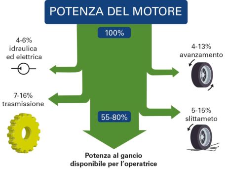
Anyway, both in case of conventional transmissions with fixed ratios, powershift transmissions and CVT, all these systems are the seat of internal frictions of various types (sliding, rolling, mixed and viscous), caused by the many machine-members in direct contact/with interposed lubricant and in relative motion (e.g., shafts on bearings, flanks of gear teeth); therefore, they constitute an important dissipation factor for the energy delivered by the motor. Considering the so-called energetic balance of a tractor, the transmission system is seat of losses that can be quantified from 7 to 16% (Figure 5) and therefore it deserves for sure an investigation.
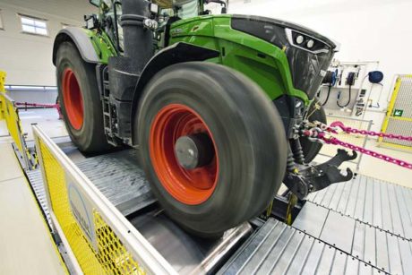
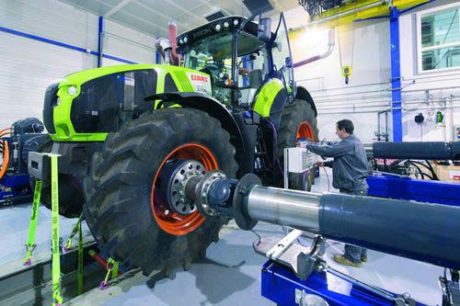
For the detection of the transmissions efficiency, it is possible to use again systems applying a controlled dissipative braking toque like those previously proposed (dynamometric brake), properly connected in a point of the powertrain downstream the transmission, for example: at the wheels (roller test stand, Figure 6, or with shafts to be directly connected with the wheel hubs, Figure 7) or at the speed-synchronized PTO (dynamometric brake used with the tractor lifted).
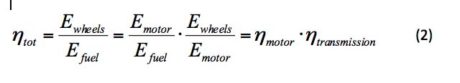
A system of this kind would allow detecting the absolute torque and power actually available at the wheels (very interesting data) and, moreover, it would permit to calculate the transmission efficiency, known the motor power output obtained from previous tests at the power take-off synchronized with the motor. For the considered systems (motor, transmission), in series one another, the following equation is valid:
Conclusions
Agricultural driving machines (and tractors in particular) are self-propelled systems with a high complexity from the mechanical point of view, especially regarding the transmission subsystem, fundamental to grant the full usability of these machines in the various tasks they are called to perform. They have also a series of mechanical interfaces (the so-called “power take-offs”), provided by manufacturers to drive many agricultural tools, which can give the experimenters an access to various points of the powertrain. Adopting a specific approach and then developing dedicated systems, essentially based on the use of controlled dissipative braking devices (dynamometric brakes) properly connected to the power take-offs or the wheels, it is therefore possible to achieve a full energy qualification of a machine, in terms of quantification of the efficiencies of the motor system and of the transmission system as well.
[su_box title=”In-depth readings” box_color=”#264a66″]Bietresato, M., Calcante A., Mazzetto, F., A neural network approach for indirectly estimating farm tractors engine performances (2015) Fuel, 143, pp. 144-154. DOI: 10.1016/j.fuel.2014.11.019. Bietresato, M., Friso, D., Sartori, L., Assessment of the efficiency of tractor transmissions using acceleration tests (2012) Biosystems Engineering, 112 (3), pp. 171-180, DOI: 10.1016/j.biosystemseng.2012.03.009. Concli, F., Gorla, C., CFD simulation of power losses and lubricant flows in gearboxes, (2017) American Gear Manufacturers Association Fall Technical Meeting, (January 2017), pp. 2-14. ISBN: 978-151085281-5. Concli, F., Gorla, C., Numerical modeling of the power losses in geared transmissions: Windage, churning and cavitation simulations with a new integrated approach that drastically reduces the computational effort, (2016) Tribology International, 103, pp. 58-68. DOI: 10.1016/j.triboint.2016.06.046. Concli, F., Gorla, C., Windage, churning and pocketing power losses of gears: different modeling approaches for different goals [Wirkungsgrad und Verluste von Zahnradgetrieben: Verschiedene Methoden für verschiedene Anwendungen], (2016) Forschung im Ingenieurwesen/Engineering Research, 80 (3-4), pp. 85-99. DOI: 10.1007/s10010-016-0206-9. Mattetti M., Molari G. Trasmissioni, il prossimo futuro è nella doppia frizione? Macchine e motori agricoli (2013), n.6, 32-34. Molari G., Pagliarani S., Perdite di potenza nei cambi full power-shift; Terra e vita (2007); n.23; 44-46. Molari G., Trasmissioni a variazione continua per trattori di potenza medio- bassa; Mondo Macchina (2012); anno XXI n.1; 84-89. Pagliarani S., Molari G., Alla scoperta delle CVT; Macchine e Motori Agricoli (2010); n.3; 42-45. Renius, K. T., Resch R., Continuously variable tractor transmissions, (2005) ASAE Distinguished Lecture: tractor design, 29, pp. 1‐37. St. Joseph, Mich.: ASAE. Renzi, M., Bietresato, M., Mazzetto, F., An experimental evaluation of the performance of a SI internal combustion engine for agricultural purposes fuelled with different bioethanol blends, (2016) Energy, 115, pp. 1069-1080. DOI: 10.1016/j.energy.2016.09.050. Bietresato M., Concli F., Mazzetto F., Come caratterizzare l’efficienza delle macchine agricole, (2018) Il Progettista Industriale – Quaderni di Progettazione, n.5, pp. 61-65.[/su_box]
[su_note note_color=”#ffcf66″]Where is it possible to study the efficiency of agricultural machines? At the Free University of Bolzano, for instance, with the following professors: – Ing. Franco Concli – SET Ph.D. School – research issue “Development of new gearbox architectures for a better system efficiency”. Contact: franco.concli@unibz.it – Ing. Marco Bietresato, Prof. Fabrizio Mazzetto – MEA Ph. D. School – research issue: “Definition of new power systems for agricultural units to be used in mountain areas”. Contacts: marco.bietresato@unibz.it, fabrizio.mazzetto@unibz.it [/su_note]


