
Ke Li, Zongxuan Sun, Mechanical Engineering Department Minnesota University, Minneapolis, MN (USA)
The free-piston engine (FPE) described in this article is a two-stroke opposed-piston opposed-cylinder (OPOC) engine that offers the highest power density and exhaust efficiency among FPE architectures.
The compression ratio is an important factor that determines the motor efficiency. Besides, the flexibility of an internal combustion engine (ICE) can notably rise if the compression ratio can vary in real time. Various mechanisms have been proposed in relation to the variable compression ratio, based on the modification of the structure of the crankshaft. The free-piston engine (FPE), however, offers the highest flexibility for variable compression ratio control, by eliminating the crankshaft. The advantage of this configuration resides in the simplicity of the structure, composed by few moving parts, resulting in a compact engine with low maintenance costs and reduced friction losses. The free-piston engine (FPE) was invented by R.P. Pescara in the Twenties of the Twentieth Century [1]. At that time, the absence of adequate sensing and control technologies did not allow attaining a reliable operation of the FPE. Recently, thanks to the development of new sensing, actuation and computing technologies, researchers have discovered the enormous potential of FPE. You can find a complete survey of recent works about FPE in [2].
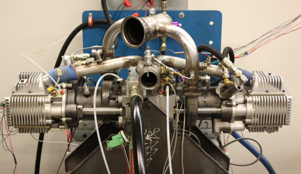
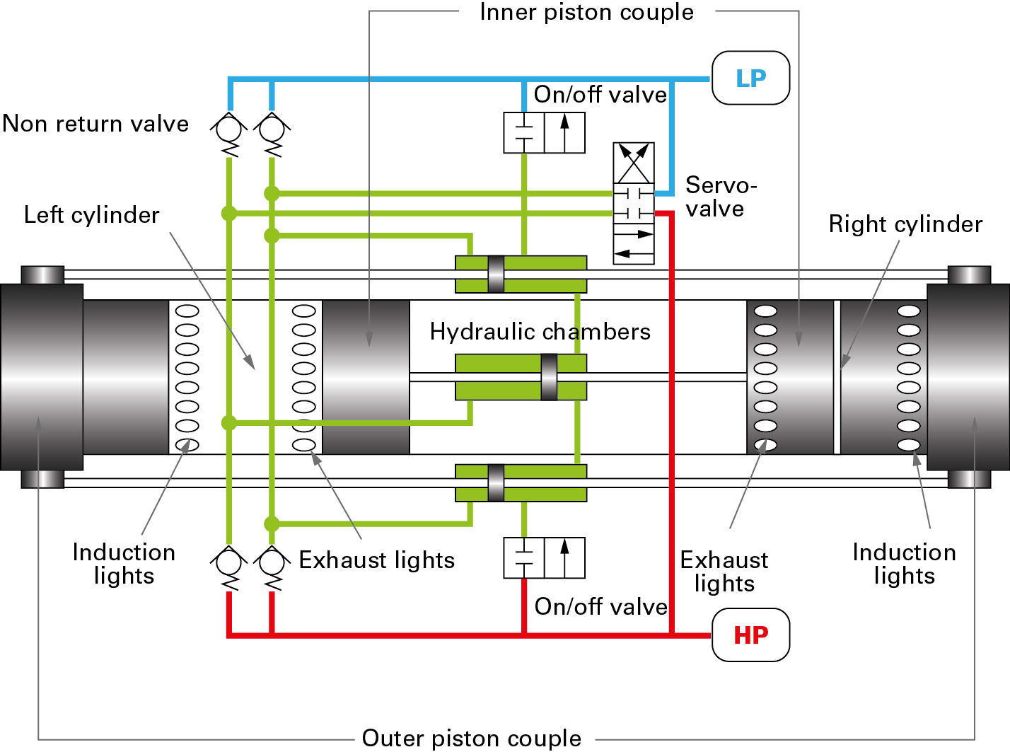
The FPE described in this article is a two-stroke opposed-piston opposed-cylinder engine (OPOC) which provides the highest power density and exhaust efficiency among FPE architectures. Figure 1 shows both a photograph and a schematic of the engine. Combustion in the right cylinder pushes the inner piston to the left and the outer piston to the right, which compresses the gas in the left cylinder. The two cylinders fire alternately while high-pressure fluid is being pumped out via the piston motion. In other words, the engine converts the chemical energy into fluid power.
This design eliminates the mechanical linkages between each engine unit and hence drastically increases the modularity of the system. Given its potential for high efficiency and flexibility, the FPE is well suited for mobile applications such as on-road vehicles and off-road heavy machinery.
Active motion control
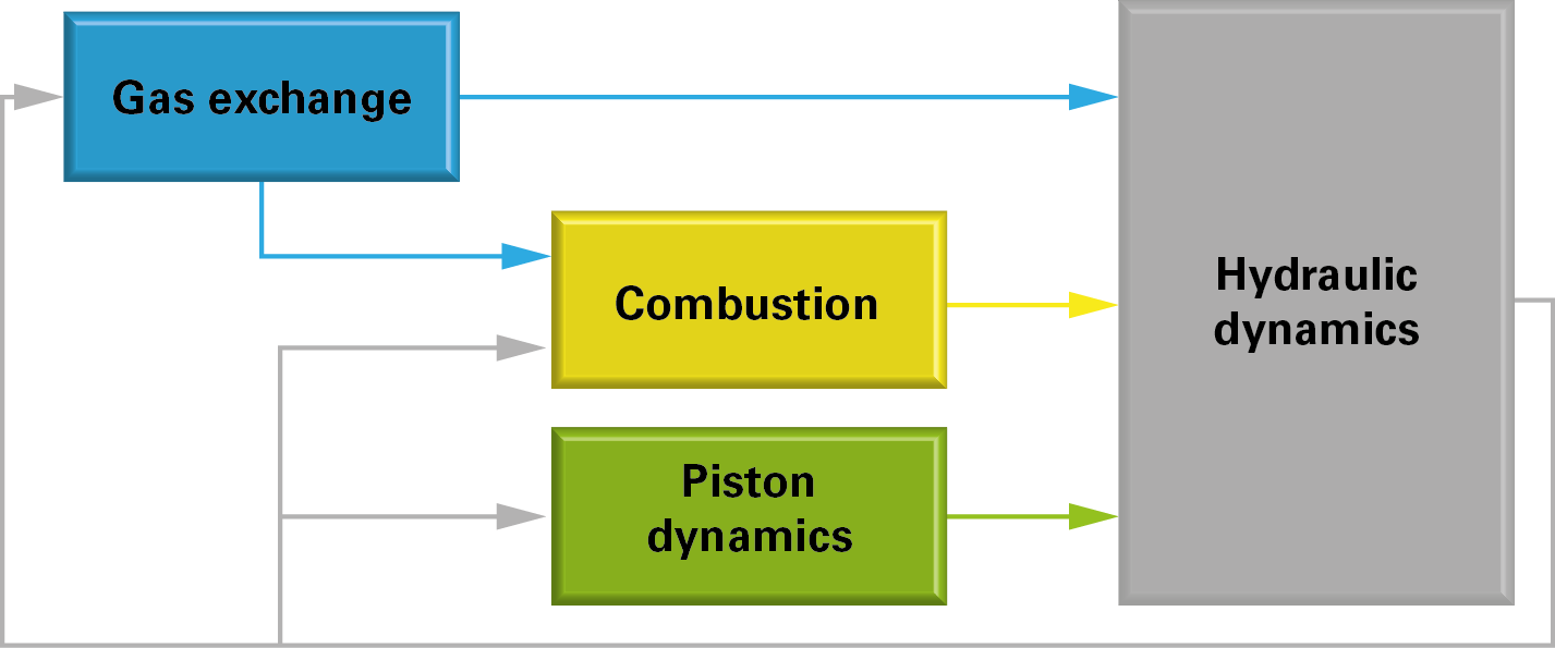
The main technical constraint for the FPE is the big variation from cycle to cycle, especially during transient operations. Simulation studies [3, 4], highlighted that the engine in figure 1 is found to be unstable at various loading conditions. This is due to the fact that the engine operation is relatively complex, so that the dynamics of sub-systems are strongly coupled, as figure 2 shows. Specifically, the piston motion affects the hydraulic dynamics, the gas mixing and the combustion process. 2. In their turn, the combustion pressure and the hydraulic pressure determine the piston dynamics.
The intrinsic nature of the engine feedback implies that the active control is essential to the ends of a stable operation. Therefore, a robust and precise piston motion controller is designed [5]. [5]. The controller acts as a virtual crankshaft that guides the piston to follow a reference trajectory via the hydraulic actuator (servo valve) by utilizing energy from the storage element. Given the periodic nature of the piston motion, the active controller employed here is of the robust repetitive type, which is capable of tracking any periodic reference signal with fast convergence rate and small steady state error.
The advantage of the active motion controller resides in its capability of tracking and modelling the piston path precisely. In particular, the reference trajectory of the virtual crankshaft can be modified digitally in real time, to obtain a wide range of piston motions and then the highest engine efficiency in the various operational points.
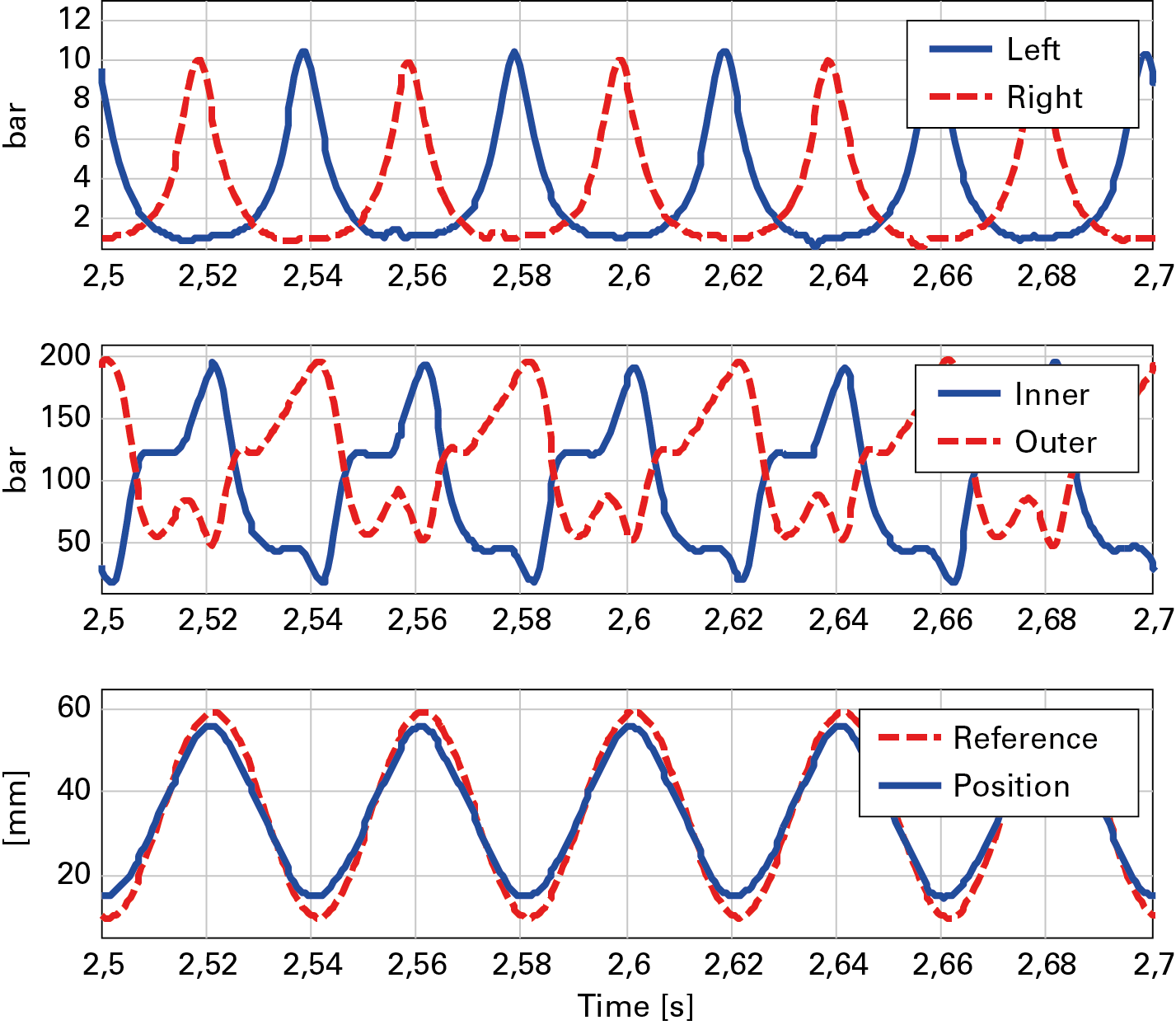
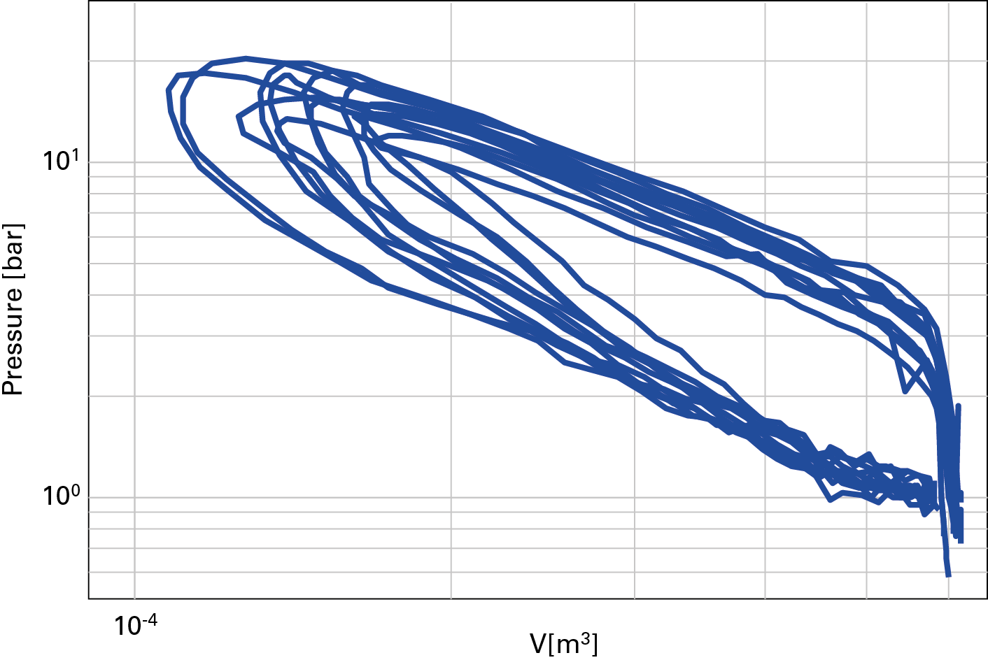
The figure 3 shows the results of mechanical tests on the engine. The virtual crankshaft is able to produce stable and repeatable motoring with precise piston motion tracking. The figure 4 shows the P-v diagrams of preliminary combustion tests. Even if we can notice a variation from cycle to cycle in the graph, the engine operation is stable and this demonstrates the effectiveness of the motion controller.
Conclusions
The FPE engine features a high potential of energy saving and control of emissions, but its operational reliability is limited by the complexity of the dynamic coupling among the engine subsystems and the absence of the crankshaft. This inherent technical barrier for FPE could be overcome by active control based on today’s sensing, actuation and computing technologies. A hydraulic FPE prototype is used to demonstrate the capabilities of active piston motion control. Experimental results demonstrate the feasibility and promise of the technology. Engine power control will be combined with piston motion control in the future, to achieve a wider range of engine operation and higher engine efficiency.
Thanks
The authors thanks the NSF Center for Compact and Efficient Fluid Power (CCEFP) for the financial support (EEC-0540834) and Ford Motor Company for donation of the free-piston hydraulic engine.
Bibliography
- Pescara, R.P., “Motor compressor apparatus,” Brevetto US, 1,657,641, 1928.
- Mikalsen R. e Roskilly, A.P., 2007, “A review of free-piston engine history and applications,” Applied Thermal Engineering, 27(14-15), pp. 2339-2352.
- Li, K. e Sun, Z., 2011, “Modeling and control of a hydraulic free piston engine with HCCI combustion,” the 52nd Nat. Conf. Fluid Power, Las Vegas, NV, pp. 567-576.
- Li, K. e Sun, Z., 2011, “Stability Analysis of a Hydraulic Free Piston Engine with HCCI Combustion,” ASME Dynamic Syst. Control Conf., Arlington, VA, pp. 655-662.
- Li, K., Sadighi, A. e Sun, Z., 2012, “Motion Control of a Hydraulic Free Piston Engine”, of the 2012 American Control Conf., Montreal, Canada, pp. 2878 – 2883.


Very interesting article. Wish I had found it sooner. How may I reach you and/or the Ford Motor Company Division that is dealing with the donated engine? I have a potential application in mind.