
Uncoupled analyses of motor and pump component
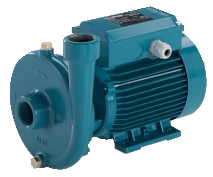
This article describes the implementation of a measuring bench for didactic purposes, constructed for experimental tests, to the ends of the study of the performances of a centrifugal motor pump (Figure 1). The bench setup, provided with a complete equipment of advanced measuring and control systems, has allowed an uncoupled analysis of the operation parameters of the pump and of the electrical motor.
Introduction
The work, carried out by the Machine Laboratory of the Engineering Department of Ferrara University, was developed in the ambit of a Master of Science thesis in Mechanical Engineering. The idea of implementing this measuring bench springs from the need of studying in-depth the hydraulic performances of this machine typology, freeing the results from the contributions not directly ascribable to the pump itself. We refer in particular to the electric motor, which is a self-standing element as to the pump and whose contribution influences the global performances of the system, needing to be monitored separately.
The centrifugal motor pump and the torquemeter
The centrifugal motor pump is a hydraulic machine listed in the sector of turbomachines, widely used in all industrial sectors and relatively cheap, realized to transfer water and liquids in general. The chosen machine typology was a small-size centrifugal motor pump, with 0.37 kW nominal power motor.
The pump is characterized by a semi-open impeller, typically used for pumping industrial waters, even moderately loaded with impurities. The energy supplied to the liquid is generated by an electric motor, which operates a transformation of the energy from electrical to mechanical. The mechanical energy is transferred by a transmission shaft to the pump and then, by the latter, converted into kinetic and pressure energy on the fluid, by a centrifugal element called impeller. Due to the presence of two separate systems, it is clear the importance of measuring in uncoupled manner the performance parameters of motor and pump, which essentially feature two different energy conversion efficiencies.
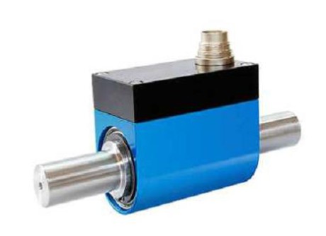
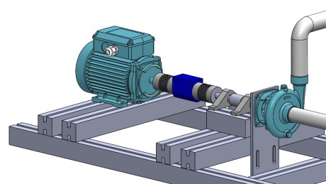
To reach this target, besides the measuring instruments for the motor and pump side, necessary for the calculation of the electrical and hydraulic energies, they have provided for a torquemeter between the two elements. Using this instrument, it was possible to execute a precise measurement of the torque actually transferred to the pump by the transmission shaft, eliminating the wide uncertainty that would be attained by calculating it indirectly, through absorption and electrical efficiency values. In this case, we should assume a hypothetical value for the efficiency, according to theoretical notions that might turn out to be distant from the reality. Being a forefront measuring instrument, the various products available on the market were examined according to the technical level. The suitable instrument, model 86-2112R-502, was selected relying also on the twenty-year experience of Burster Italia, at Curno (Bergamo, Italy), concerning torque sensors and related coupling joints. An image of the instrument and the assembly scheme are presented in Figures 2 and 3.
Pump and electric motor performances
The performances of a centrifugal pump are assessed by three parameters:
- Flow rate = it is the operation liquid volume conveyed by the pump in the time unit. The measuring unit of this magnitude is typically [m3/h] and measurements can be executed in various manners. The weighing method, used in our study and described in detail inside the UNI EN 24185 regulation, consists in executing the flow rate measurement in a closed duct, by weighing the liquid mass conveyed into a tank equipped with a balance, in a defined time interval. The flow rate varies according to the revolution number of the pump;
- Head = it is the output that the pump transmits to the liquid. The head calculation derives from the mechanical energy equation. Considering the delivery and intake sections at the same height and with the same sizes, the equation is simplified and the head H, in [m], is determined by the following formula: H = Δp/ρg , where Δp is the pressure difference between input and output sections, measured in [Pa]; ρ the density of the liquid processed in [kg/m3] and g the gravity acceleration in [m/s2].
- Total efficiency = it is the ratio between the power supplied to the fluid and the one absorbed by the pump. The efficiency formulation is the following: Ƞpump = ρQgH/P
Where Q is the flow rate at the output section in [m3/s] and P the power absorbed by the pump in [kW], calculated as , with C torque in [Nm] measured by the transmission shaft, ω shaft rotation speed, in [rad/s].
For the motor, too, they have estimated the total efficiency, which considers the energy transformation from electrical to mechanical. As in the previous case, the efficiency represents the ratio between mechanical power supplied and the electrical power absorbed by the motor. The efficiency formulation is the following: Ƞmotor = P/Pel
Measuring and control system
The complete measuring bench is shown in Figure 4. The main components and the measuring and control instruments used are described, as follows:
(*) The inverter, model Starvert iG5A by LS Electronics, was supplied by Ferrara University free of charge. The Korean LG company, owner of LS, in case of use for didactic purposes, applies a free shipment and use policy for some items.
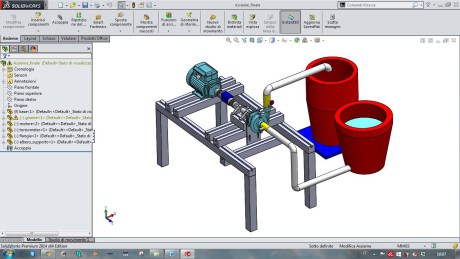
- Electric motor. Electrical connections have been equipped with current clamps to monitor the absorbed power. Besides, the motor has been connected with an inverter (*), by means of this control instrument it is possible to vary the value of the electrical excitation frequency and to adjust the revolution number;
- It measures the torque actually transferred from the motor to the pump and the rotation speed of the shaft, being available on this model also the angular measurement detection. The instrument, characterized by a broad measuring precision, has the 0.02 % full-scale accuracy, corresponding to ± 0.004 [Nm]. The coupling to the transmission was implemented by apposite joints, they too supplied by Burster Italia. Bellow-type joints assure an integral coupling and allow the torquemeter assembly even in presence of small misalignments;
- Intake and delivery ducts have been instrumented with pressure sensors to measure the Δp between input and output of the pump and to determine its head. The delivery duct is equipped with a gate valve, to simulate the load losses of the plant and to range on the entire flow rate-head curve;
- Load tanks. The two tanks perform the function of supplying water to the pump and of measuring the processed liquid quantity. The measuring tank, which receives the liquid, is positioned on an electronic balance. The chronometric and liquid volume measuring allows determining the flow rate.
Characteristic curves, torque and efficiencies
Through measurements carried out by the test bench, it was possible to determine the characteristic curve flow rate – head of the pump, for various rotation speeds.
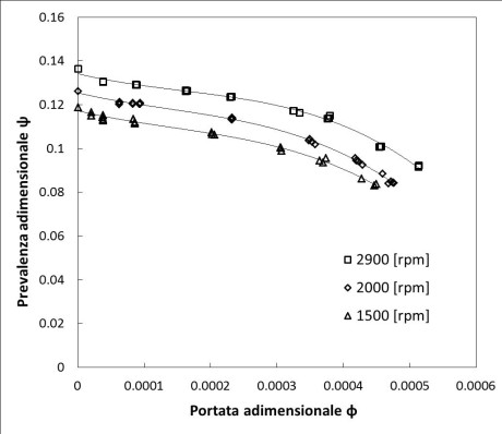
Figure 5 shows the relative graph, with the values of Q flow rate on the abscissa axis and of the H head on the ordinate axis. Both magnitudes have been treated as non-dimensional.
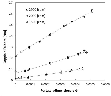
The graph in Figure 6 shows the torque values, in [Nm], measured by the torquemeter on the transmission shaft between electrical motor and pump. Values always depend on the non-dimensional flow rate and curves are traced for the three rotation speeds considered. Knowing the mechanical torque actually delivered by the motor and the rotation speed of the shaft, they calculated the exact power transferred by the electric motor to the pump and consequently it was possible to draw the separate efficiencies of the two components. Through the analyses carried out at the test bench, supported by the high technical level of the adopted instruments, the hydraulic pump performances have been studied in-depth. Succeeding in isolating the hydraulic pump performances, this work lay the bases for an advanced use of the bench, such as the development of new components and technologies applicable to centrifugal pumps and to hydraulic machines in general.
For further information: www.burster.it
Bibliography
- Negri di Montenegro Giorgio, Bianchi Michele, Peretto Antonio (2009) – Sistemi energetici e macchine a fluido. Vol. 1.
- Giuseppe Cantore (1999) – Esculapio.
- KSB Aktiengesellschaft – Selezione delle pompe centrifughe;
- Burster – Technical data sheet


