
– Giorgio Paolo Massarotti
ImaMoter-Cnr, Cassana (Ferrara, Italy)
Certainly we all have had the experience of taking a train, maybe a high speed one, and we have certainly noticed that during the travel the train moves without particular bumps and very smoothly, almost as if it “levitated” on rails. All that is possible because in the track location phase (and in the maintenance phase), it was used a machine able to keep under control the height level of the track, modifying the vertical or the horizontal dimension when needed. The machine at issue is the tamping plant.
The railway tamping machine is a plant for the ordinary and systematic maintenance of the railway line superstructure. Its function consists in carrying out the track tamping, that’s to say in bringing it to the level required by structural specifications. The operation is similar to what we commonly do with pillows in goose feather or wool when we want to give them a new shape, before falling asleep.
The tamping machine performs its task by means of hammers or arms that, introduced at specific intervals inside the crushed stone ballast close to the rail that is lifted, vibrate and move in order to tamp the crushed stone and to lift it at the desired height. With this process the plates or cavities that naturally remain in the ballast are eliminated and the track is made linear, therefore safer and more comfortable, for the passage of trains.
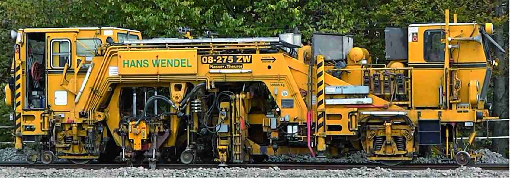
In the opening photo it is possible to notice one of the several existing architectures of tamping machines: the instruments that are involved in the tamping operation (arms) are centrally positioned under the writing “Hans Wendel” together with the alignment device of the railway line positioned more ahead. The movement of the arms and of the alignment equipment is carried out by means of a hydraulic plant operated by a control unit that decides times and modalities of the tamping cycle. The structural geometries of the control mechanics of arms depend on whether the machine is used on a rectilinear path or in curve or on points.
The tamping equipment
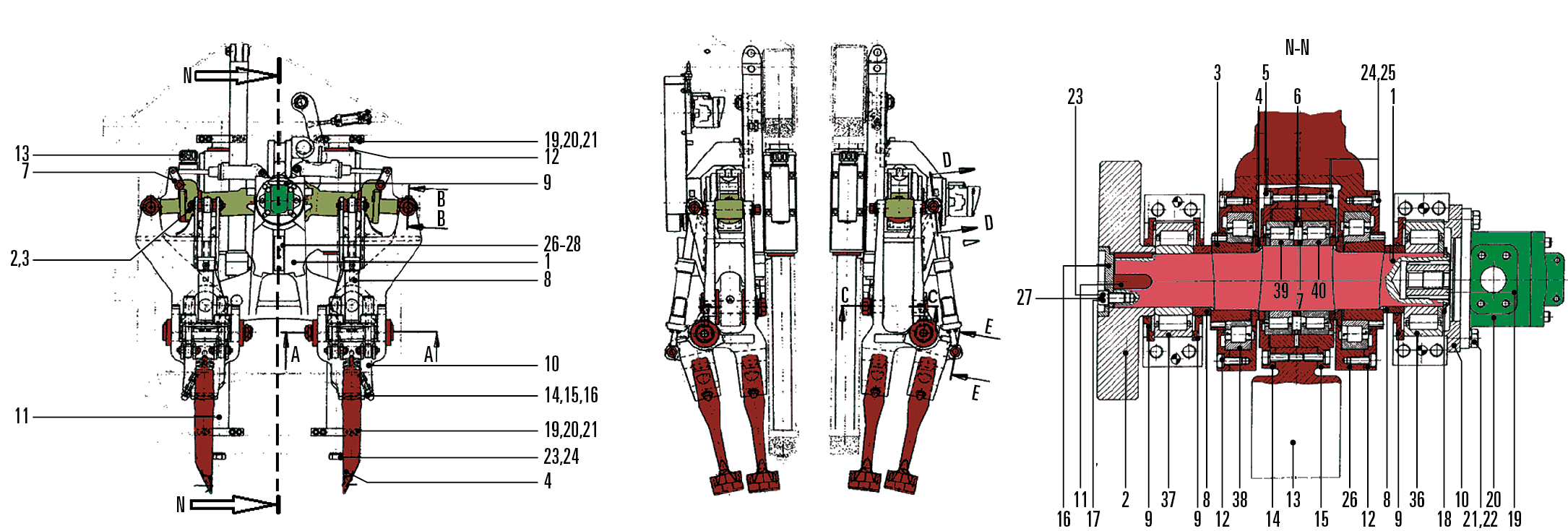
The tamping system must have the possibility of translating vertically and of vibrating: consequently, the arms will be mounted on rods hinged on an eccentric shaft system; the keying with a hydraulic motor allows the motion of the arms in relation to the axial misalignment and the rotation speed (controlled by electrical-hydraulic system) gives the required vibration frequency.
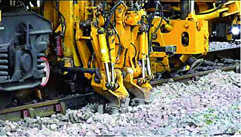
In figure 1 it is possible to notice the arms stuck into the ballast among the sleepers that bind the track in height and alignment. The figure 2 shows a structural design of the tamping equipment: we can see the arms (in red in the top image in the centre) and on the right the system with the eccentric shaft keyed to the hydraulic motor (in green). At this stage it is interesting to understand how the tamping machine operates in its totality, shortly explaining the working cycle and how inputs (and what) are given from the outside.
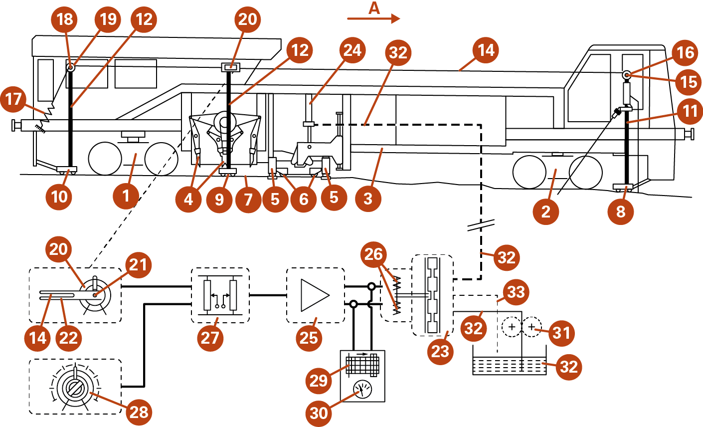
According to the design shown in figure 3 it is possible to distinguish the various components constituting a railway tamping machine. The number 3 identifies the machine frame that is lifted by carriages with double axis 1-2. The arrow A indicates the motion direction during the tamping phases of the ballast. The railway track is identified by the number 7: the latter is composed by lines, by sleepers and by the ballast. All this constitutes the roadbed. We find centrally the track alignment and lifting systems, which are identified by the numbers 5 and 6 and which allow lifting the track by means of the jack 24 fed by the 32’ pipe. Behind this under-machine we find the real tamping system, constituted by the arms 4. The detection of the track height is carried out by some pads (8, 9, 10) that, laying on the tracks, survey the difference between the length already tamped and the one still to be tamped. The pads are constrained to slide as to the vertical axes and are actually integral with some rods (13, 11, 12) that support a wire (14), which determines the line (the difference in height in this case) of the analysed track.
The hydraulic scheme
Going into further details we report (fig. 4) the circuital scheme with which parameters are set and the hydraulic adjustments of the machine occur. The bar n° 12 is connected with the rotary potentiometer 20, on whose shaft 21 is keyed the fork 22 in which slides the wire 14. The latter is constrained to the frame by means of a pretension spring 17. At their end, rods have some pulleys 18. The number 28 indicates a potentiometer that can be set by the operator in order to create an offset value. The module 27 corresponds to a differential unit that operates a logic difference among signals coming from the potentiometers 20 and 28. In the position 25 is located a signal amplifier that detects the differential module output result and amplifies it in order to operate the solenoid 26 of the servo valve 23 (in the scheme it refers to an open centre valve). The valve is fed by a feeding group that is described by the pump 31 and by the tank 32. The current that acts on the coil of the servo valve can be kept under control by means of an analogue visualization device 30 and by a registration system (pen-nib type) that allows creating a report of the servo valve actuations and, consequently, of the tamping level to which the railway superstructure is subjected. The tamping machine, passing in a slightly sloping tract, will allow the carriage 8 to detect this slope (front part of the machine); this will cause a deflection of the wire 14 that will influence the relative position of the fork 22 and of the potentiometer 20; the change of position will cause a variation of the voltage level across the differential module 27. The latter will calculate the mathematical difference between the signals of “real time” and of offset previously set by the operator with the knob on the potentiometer 28.
The height change will result in an unbalancing of the input voltage on the 28 and it will proportionally open the servo valve 23 by means of the coil 26. The opening orifice will lead to a feeding of the jack 24 that will lift by that quantity (proportional to the transduction signal from the potentiometer 20) and the tamping system 4 will execute the repositioning (or the upsetting) of the ballast under the sleepers with a control feedback dictated by the pad n°9, which will establish, in this stage, the tamping time, in order to bring back the unbalance signal to the 0 value. Therefore the level (intensity) of the tamping operation can be summarized in the time with which the arms remain inserted into the ballast, pressing it hydraulically, and in the vibration intensity given to them.
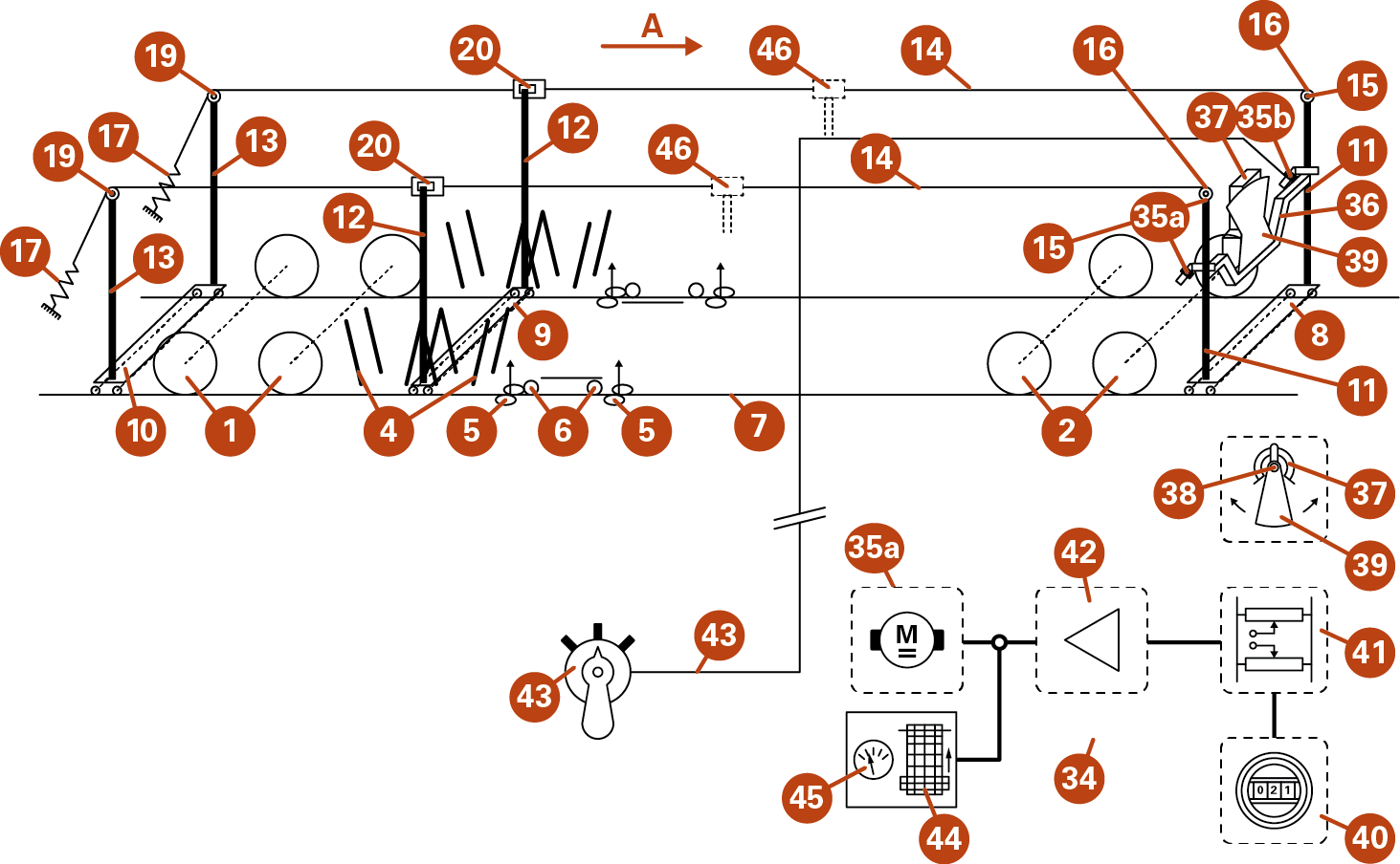
It is worth noticing how the levelling system is mechanically decoupled between right and left side in order to carry out different tamping operations on the two sides. A fundamental aspect of these machines is in fact the need of restoring the ballast level also in curved tracts. Actually in high speed lines, to allow trains to travel them at high speed, the track height from the ground is always bigger than the other; in this case, if we want to carry out the tamping operation, it is necessary to maintain the arms of the right equipment independent from the left ones. In figure 4 we can schematically notice how this occurs: we still notice the rods connected with the carriages; besides, it now possible to observe a pendulum 39 mounted on the shaft 38 of the potentiometer 37. The pendulum is kinetically integral with the crossbeam 36, which is connected to the rods of the carriage 8 on the front part of the machine. The height change (now referred to the side) will determine a rebalancing of the pendulum that will operate the potentiometer 37. The circuit shown in figure 4 reports the presence of a differential module that, as for the previous figure, makes the difference on the input signals coming first of all from the manual potentiometer 40 (selected by the operator with a reference value established by experience). The output signal from 41 is amplified (42) and introduced into the servo-motor 35a that performs the height change on the sides in order to lift one as to the other. The figure does not show the automation circuit of the motor 35, it is anyway clear that the system must lift the track on the side showing the unbalance in comparison with the other, so that at the end the common height value is achieved even if one side is not higher than the other. Nevertheless, the latter condition might be researched in curve as previously explained and then the operator will select the height value on the potentiometer 40, so that the system will try to restore the zero and consequently lift one side as to the other.
The correct positioning of the railway lines, anyway, is the fruit of the experience that the operators of these machines exploit in how and how much to set the regulation potentiometers. Therefore, all that concerns the travel quality of a passenger coach depends on the quality of the “energy” that the “tamping operator” succeeds in giving to the levelling instruments of the ballast.
For further information: www.imamoter.cnr.it


