
 Innovating in inlets; new technologies to meet emissions legislation for heavy diesel engines.
Legislation to control diesel emissions has become ever more stringent, with increasingly harsh penalties for operators of vehicles which do not comply. With the twin aims of minimising particulates and nitrous oxides (NOx), the new Euro VI standard comes into force in Europe at the end of 2013, while the EPA13 demands similar standards in the US. For trucks and buses, Euro VI sets a maximum of 1.5 g/kWh of soot and 0.4 g/kWh of NOx.
The emissions levels for NOx are five times lower than those stipulated in the Euro V standard which has been in force since October 2008. This places more and more significant demands on engine and after-treatment system designers to incorporate technologies to minimise emissions.
Three main ways of minimising emissions
Currently, there are three main ways of achieving this. Exhaust Gas Recirculation (EGR) systems reduce the quantity of available oxygen for, and the temperature of combustion and therefore the amount of NOx generated.
Aftertreatment solutions can also be used. Selective Catalytic Reduction (SCR) entails the introduction of urea into the vehicle’s exhaust system, where it reacts chemically with exhaust gases in combination with catalysts to minimise the presence of NOx.
Finally, vehicles can be fitted with soot filter which traps particulates and then burns them off using an integrated flame generation system. Both the SCR and soot filter systems are located at the end of the exhaust pipe directly before exhaust gases leave the tail pipe.
To meet the new Euro VI standard, it is common practice to employ all three of these technologies. However, to incorporate all three of these systems into a modern diesel engine and have them operating at optimum efficiency and effectiveness creates a further requirement – namely to precisely control the flow rate of air into the entire engine and exhaust treatment systems.
This is because SCR systems, and the catalysts within them, must be maintained at a high temperature – typically at least 200ºC – to operate effectively. Periodically the exhaust temperatures need to be above around 300°C to establish a flame in order to burn the trapped soot, a process called active regeneration This is a particular issue in vehicles operating in urban areas or ‘multi-drop’ routes, where system temperatures typically remain cooler than in vehicles operating on inter-city drive cycles . In these instances, pollutants are not always converted into harmless by-products sufficiently, or the filters are not able to regenerate, meaning the vehicle becomes non-compliant and the vehicle control system must then limit the engine to ‘de-rated power’. It is therefore imperative to be able to raise exhaust temperatures, as required, with the minimum additional consumption of fuel.
Meanwhile, for EGR systems to operate optimally, exhaust pressures before the turbo need to be maintained above the inlet charge pressure after the turbo. In some operating situations it is now necessary to throttle the inlet air to force a positive pressure gradient for EGR.
A number of strategies are available to deliver this. Vehicles with variable geometry turbochargers (VGTs), whose vanes can be physically moved, can to some degree heat up the exhaust and adjust the pressure within the EGR system. In combination with an exhaust throttle or exhaust brake, this set-up can deliver the level of performance required to meet Euro VI. However, fuel consumption is often increased when an exhaust throttle is used.
Another alternative – but one which is only likely to be effective on vehicles operating on long-haul routes – is to operate SCR at the very highest conversion level, which can achieve the emissions standard without EGR. However, this will add significantly to urea usage and still requires exhaust temperature management when operating at low loads or during cold starting.
What is ideally needed, therefore, is a system which can manage the flow of inlet air into the system, assist EGR as necessary and manage exhaust temperatures with minimal impact on fuel consumption. This can be achieved using an air inlet throttle.
Seeking to ‘upscale’ air inlet throttle technologies
Some system designers in this area have taken the route of seeking to ‘upscale’ air inlet throttle technologies originally developed for passenger cars typically from petrol engines. While these systems have been approved by some of the less demanding vehicle manufacturers, independent tests have raised significant question marks over their ability to meet the more severe operating conditions required of heavy duty engine applications.
Initially pneumatic actuation was considered for these throttles, being a common method for actuating exhaust brakes for the last decade. However, the lack of speed and precision, and high air consumption associated with pneumatic actuation, meant that this approach was dropped in favour of electric actuation. Furthermore, pneumatic components are frequently subject to ‘overshoot’, moving past the required operating angle and then correcting themselves – rather than offering the precise movements needed to cope with specific operating requirements. Given the move in general towards electrical components in engines, such as for turbochargers, and the recent availability of high performance brushless motors, electric inlet throttles have become the standard.
The latest innovations in air inlet throttles are ‘smart’, meaning they have local control and condition monitoring and communicate with the vehicle network via CAN. -They use a proven DC brushless motor directly coupled to a throttle body and air control flap designed specifically for commercial vehicle applications. Receiving cooled air from the charge air cooler, the inlet throttle ensures that air is precisely metered into the engine and exhaust treatment system to ensure optimal functioning. This delivers benefits in a number of key performance areas.
The first is in the maintenance of high exhaust temperatures, to ensure optimum temperature of SCR catalyst, and to initiate filter regeneration with minimal additional fuel consumption.
Secondly, the inlet throttle optimises the pressure gradient driving EGR, allowing the best “in cylinder” combustion conditions under a wide range of operating modes. Thirdly, it can be used in conjunction with other controls to optimise soot combustion during filter regeneration.
Fourthly, it can assist in the cold start of emissions components, reducing the amount of oxygen available to them, in much the same way as a choke on a petrol engine.
Finally, the inlet throttle has an additional benefit, forcing immediate shutdown on key off, eliminating the ‘run-on’ which is commonly found in modern high-compression engines, furthering driver comfort.
To deliver all of these benefits, the inlet throttle must meet a number of key design parameters. First and perhaps most important is speed, with an operation time of as short as 100ms desirable. Secondly, it must be ‘high-resolution’, delivering precise flow control to through precise flap positioning to tolerances of 1/4°, or less. The product must also be superdurable with the ability to withstand 10 million cycles or more. Sealing capacity is also key, in order for the engine to be shut off immediately on demand. Just as important, however, the inlet throttle must never shut off the engine unintentionally, meaning it must automatically return to the open position under its own spring force in the event of any potential failure mode. The performance level demanded of these systems requires the use of a compact and durable motor with a very high power density.
A number of other key features are achievable in this system type based on its ability to perform its own condition monitoring and then automatically take corrective action. A common risk of throttling inlet air in adverse climatic conditions is the potential to form ice. For this reason, if such conditions are detected, the valve can be agitated rapidly to shake off any ice accumulation while in cases of ice build-up, has a ‘hammer’ function to break off any ice which has formed in the throttle. In extreme cases the valve can switch itself off and attempt to reactivate at regular intervals.
An optional ‘wake-up’ function can also be integrated, enabling the valve to start operation before the engine is switched on, and operate after the engine is switched off.
Leading systems of this kind incorporate steel gears for enhanced durability as opposed to plastic , while special FKM Viton seals, stainless steel valve elements and special housing coatings are used in order to resist the corrosion which can be caused by the development of acidic condensates from exhaust residues. An operating range of between -40°C and +140°C is achievable, entailing the use of sophisticated greases capable of coping with these extremes of temperature. Meanwhile, further innovations in design have been necessitated to ensure these new systems fit compactly into the different engine spaces available.
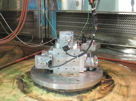
These operating capabilities can of course only be guaranteed following extensive and highly stringent testing. Modern vibration tests, for example, involve the subjection of valves in various orientations to many hours of highly amplified accelerations while operating and also being subjected to temperature variations.
The issue of vibration and its impact on physical performance and service life has driven some key advances in design. The use of opposed angular contact ball bearings is established to eliminate free ‘play’ in bearings and so better combat the effects of vibration by preventing fretting and knocking. However, the latest bearing systems also incorporate o-rings in their cases to stabilise them further, also ensuring a very consistent meshing distance between the gears.
Meanwhile, each component has to be designed so it will not be affected by critical natural frequencies. Thermal cycling and shock testing to assess the performance of products when subjected to sudden changes in temperature- plunging the unit alternately into ice and then boiling water is the usual format – are also key in determining the point at which units leak or crack, or seals start to fail. Pressure leak testing – to both positive and vacuum pressures – provide a guide to performance under different operating conditions, while modern corrosion tests involve subjection to the effect of a range of acids to determine their effect on seal performance and unit integrity.
However, perhaps the greatest challenge is in ensuring repeatability of performance between individual valves. The placement of the flap in the tube is critical here as this governs sealing quality and leakage potential. Manufacturers are constantly reviewing how to optimise repeatability but key to this is the end of line torque signature.
Inlet throttle technology is already making its first appearance in ‘incentive engines’ being fitted into vehicles to be purchased by ‘early adopters’ of the Euro VI standard.
Find out more at http://www.norgren.com/uk/commercialvehicle


