
Antonino Bonanno, Imamoter-CNR, Cassana (Ferrara, Italy) –
Quite simple industrial equipment, like a “cyclone”-type particle separator, can give birth, when studied with numerical analysis techniques, to computational difficulties of some significance. This article tries to demonstrate that what seems “simple” is not always, at the same time, “easy”.
Cyclones are industrial equipment used to separate solid particles from a main flow that can be constituted by a gas or by a liquid.
Particles away
Cyclones are commonly used as “sand collectors” in irrigation plants to separate the sand from the water extracted from the underground. Still cyclones are used in different industrial ambits (ceramic, cogeneration, waste disposal) to purify exhaust gases, or the air extracted from working environments, from the particles dissolved in it that cannot be dispersed in the environment.
In the design of a cyclone the key target is quite simple: to obtain the best filtering efficiency with the lowest pressure drop. Cyclones do not provide for moving parts: they exploit the fluid speed or the difference of density between the solid layer and the gaseous one to separate the first from the other. The cyclone is therefore a machine that can operate in continuous, with simple structure, characterized by the possibility of operating also with fluids at very high temperatures and it does not need any periodical maintenance.
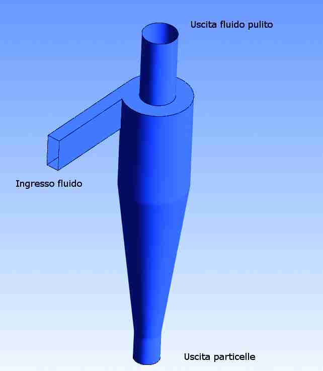
The secret of the functioning of a cyclone is connected with its shape.
Cyclones are characterized by a cylindrical part (the top part) into which is injected the compound to be separated tangentially to the walls themselves. The bottom part of a cyclone has typically conical shape, at the end of which the solid phase is deposited and removed. Under the influence of centrifugal forces, the phase with bigger density is pushed towards the bottom in the conical section of the cyclone. The lighter phase migrates instead towards the top. The flow, inside the cyclone, takes the form of a primary vortex directed towards the bottom and the solid deposits on the walls, becoming concentrated on the bottom. The gas escapes instead from the top, through a coaxial pipe of the equipment, originating a secondary central vortex.
The solid-gas separation processes can occur by steps or as result of a single process. Depending on the quantity of solid to be separated, the devices can have big physical sizes and, to be able to limit process costs and to reduce the physical space taken up as much as possible, the efficiency is expected to be as high as possible. As already said, the equipment operates in continuous and it is very simple from the structural point of view, it can operate also on hot currents and can recover particles with sizes exceeding 0.01 mm. The inlet speed of the gas is high (10-30 m/s) and the recovery capabilities (but also the load losses) increase hand in hand with the rise of the gas speed and the decrease of the cyclone diameter: to limit the load losses to the usual value (100-200 Pa) it is possible to use multiple units in parallel.
Fluid-dynamic analysis of the cyclone
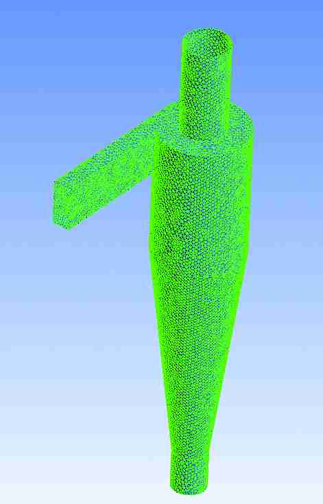
The study of the efficiency of the phase separator was carried out by means of computational fluid-dynamic techniques, also known as CFD, from the English Computational Fluid Dynamics. The fluid domain to be solved is subdivided into sub-volumes (cells) and to each of them are applied the laws of Navier-Stokes equations that represent the conservation of the momentum, of the mass and of the energy. The minor are the sizes of the cells of the calculation grid and the higher will be the accuracy of results, to the detriment however of the calculation time. In practice, the resolution of calculation grids is thickened in the regions of importance. In almost all the cases of practical application, the motion of a fluid is characterized by the presence of turbulent motions. These lead to the formation of vortexes that subtract energy to the main motion of the fluid. Those vortexes decompose giving rise to vortexes of smaller sizes and we will have moreover the formation of smaller and smaller vortexes until when the energy of swirling motions is dissipated by forces of viscous nature. We have then an energy transfer in cascade from the main fluid up to smaller vortexes. To be able to solve fully a turbulent motion, it would be necessary to subdivide the fluid domain into elements as small as they are the vortexes having minor dimensions.
Despite the capability and the power of current computational computers, the direct resolution of Navier-Stokes equations (DNS Direct Navier-Stokes) turns out to be unfeasible for the majority of the cases of industrial interest. To solve the problem, they have implemented in modern calculation software the so called turbulence models that are based on the assumption that the speed in turbulent motion is characterized by the fluctuation of the same around an average value. One of the most common models, widely used in the modern industry, is the so-called k-Eplison model. Without going into too much detail, in this article it is sufficient to specify that the k-Epsilon model shows scarce reliability in presence of flows characterized by high curves, just as it happens in cyclones. To get out of such limits, they have used the SST (Shear Stress Transfer) turbulence model that, permitting not to overestimate the turbulent mixing in the limit state (the one formed close to the still walls of the container where the analyzed fluid moves) allows avoiding the excess of production of turbulent energy that characterizes the other methods and leads to false results.
Interaction between fluid and particles
The main problem in the study of particle separators is represented just by the interaction between two physically different substances, a gas (or a liquid) and a solid dispersed in it. Various scholars have tried to address the problems just restricting themselves, in large part, to the fluid-dynamic study of the only gaseous part, neglecting in other words the presence of particles. What we are presenting here is one of the first attempts in which the presence of a solid state dispersed into the fluid is not neglected a priori.
To be able to model multiphase systems, it is possible to apply two different approaches, the Eulerian method and the Lagrangian method. In the Eulerian method, one of the two fluids is considered as continuous while the other fluid, generally the one with minor component, is considered as a dispersed fluid. In the case under examination, also the solid phase is modelled as if it was a continuous uniformly distributed inside the gaseous phase. With the Eulerian formulation, both materials constituting the flow that enters the cyclone, gas and solid, are represented in such a way that in each point of the domain the speed ranges are known at each instant. Once solved the problem, the solver will calculate the paths of the particles drawing them from the speed range.
The other method, the Lagrangian one, represents the gaseous phase still with the Eulerian formulation, while the dispersed phase (solid in this case) is studied considering not only speeds, but also the particle trajectories, as known. Each solid particle represents a percentage of the total mass, therefore the higher will be the number of released particles the higher will be the accuracy but to the detriment of the calculation time. One of the disadvantages of the Eulerian method is given by the fact that only a particular dimension of particles can be simulated while in the Lagrangian formulation it is possible to specify a variation of the particle sizes.
The simulation of multiphase systems by using the Lagrange approach implies the injection of packages of sold particles, in which each package represents a fraction of the total mass. The bigger is the number of representative packages the better will be the approximation to the real system. In the present case test simulations with 500, 1000 and 1500 particles respectively were launched. By varying the number from 500 to 1000, it was surveyed a minimal difference of parameters of interest, which means that the number of particles considered is sufficient to have results not influenced by this parameter. The magnitudes taken as references for the assessment of the validity of the solution attained were the mass balances of gas and solid through the input and output surfaces of the model. The variation of solid and gaseous mass was around 1%, rising from 500 to 1000 particles. Relying on a good availability of computers in parallel, to be sure of the solution independence from the number of particles and to avoid further using time for that study, a precautionary number of particles amounting to 1500 was chosen.
Simulated cases
A total of 5 cases were simulated as listed in table 1. In the first case, by using the project data and the dimensions drawn from the sizing according to the literature, it was hypothesized that all solid particles contained in the flow passed to the phase separator. This condition, however, gave rise to convergence problems just determined by the big concentration of solid particles. As a matter of fact, generally, in a multiphase simulation, the number of necessary iterations to obtain the convergence varies in an interval included between 1000 and 2000. In the present case it was observed that, at full load, after a calculation time of one week and 5000 iterations, the value of residues oscillated around 10-3 without showing any tendency to converge, and therefore at that point the simulation was interrupted.
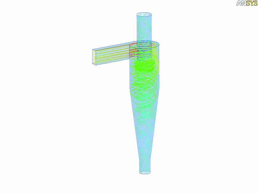
It was decided, then, to investigate the reasons at the base of this results, considering much lower, and gradually increasing, mass flow rates. In that way it was searched the maximum simulation limit permitted by the model used. In the first analysed case, the mass fraction of the solid reduced phase was obtained by multiplying the initial value by a reduction factor corresponding to 0.05. The solid mass was gradually increased up to a 0.6 reduction value, that’s to say 60% of what originally provided for. With this flow rate value, we succeeded in obtaining the model convergence but after a rather high number of iterations, about 2000. The convergence, unfortunately, was reached only up to a reduction factor of the incoming flow rate equal to 0.6. Further studies are in course, both in terms of mesh optimization and assessing other parameters that might affect the outcome, to achieve the convergence with higher flow rate values. As we can notice by observing the figures 3, representing the trajectories of the solid particles inside the separator, their distribution turns out to be more uniform at high concentrations. The effects of the particles on the speed range justify then the correct choice of the model totally coupled (Lagrangian) to the detriment of the Eulerian one, simpler but less precise. All that leads us anyway to ponder what stated in the introduction of this article; the anisotropic nature of the phenomena occurring inside a cyclone are complex, even if the machine has a simple construction and further efforts will be necessarily made to improve the modelling of systems of this type. As it turned…
| Tab. 1 – Different analysed cases | ||
| Case | Turbulence model | Factor of flow rate reduction |
| 1 | Lagrange | 1 (Full load) |
| 2 | Lagrange | 0.05 |
| 3 | Lagrange | 0.1 |
| 4 | Lagrange | 0.2 |
| 5 | Lagrange | 0.6 |


