
Olof Calonius, Panu Kiviluoma, Petri Kuosmanen –
In many applications, the technology of air supports can become a very competitive alternative to the technology of hydrostatic supports.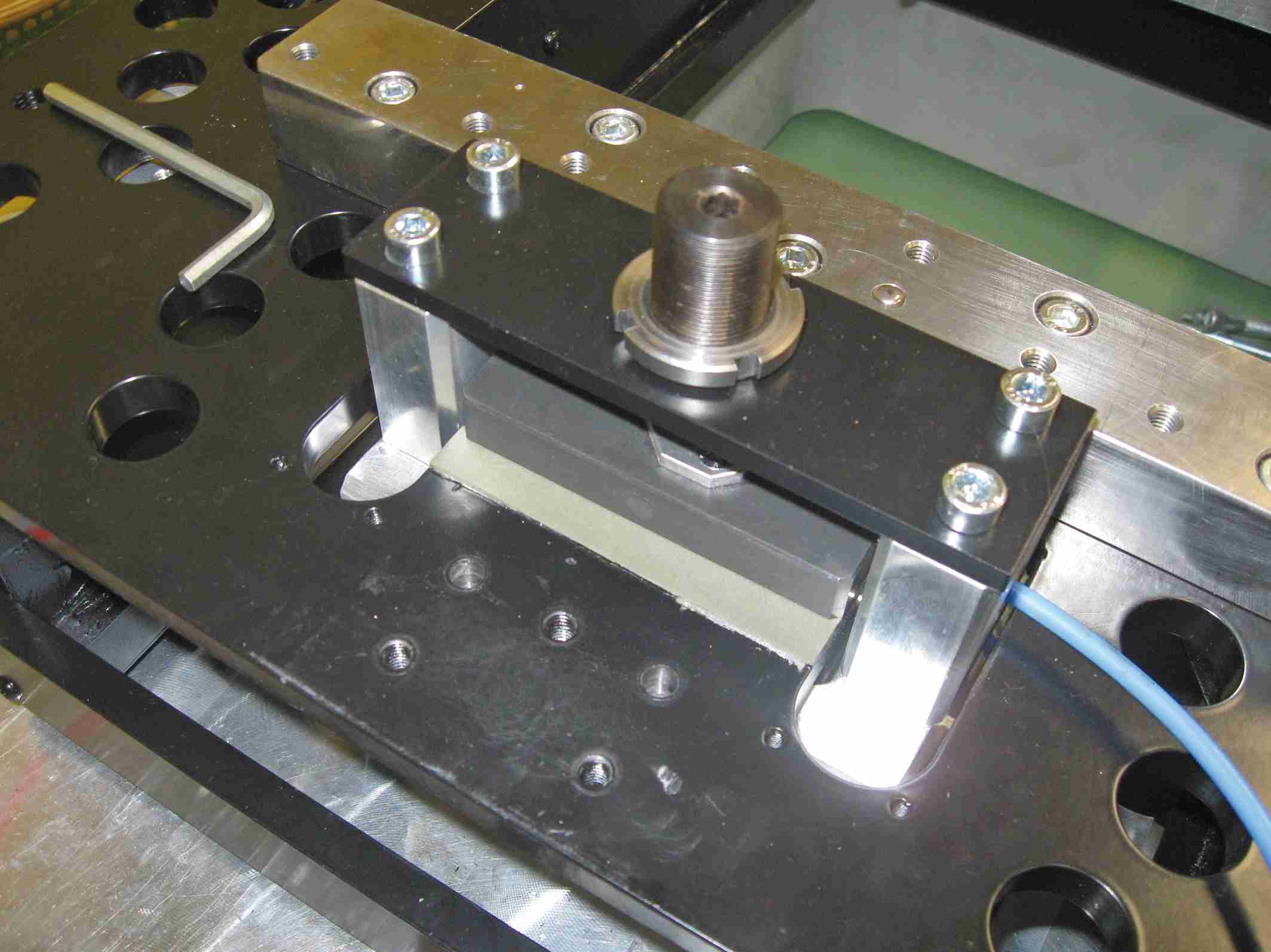
In industrial processes, the technology of air supports can become a very competitive alternative to the technology of hydrostatic oil supports where it is necessary to reduce friction (frictionless) and to have precise motions.
Besides, there are air bearing supports used to move heavy loads along the irregular factory surfaces. This type of air bearings is not however optimized for the operation in continuous, the practicable distance and the transport time are limited and the big air consumption is not acceptable. Among the air bearings, porous material supports have achieved growing success thanks to their contact tolerance during operations and the low air consumption. The purpose of this study is to explore the possible uses of these supports in industrial applications that involve moderate sliding speeds, moderate quality of contrary surfaces, a very wide tolerance and a dynamic load.
Test bench, support loading and alignment
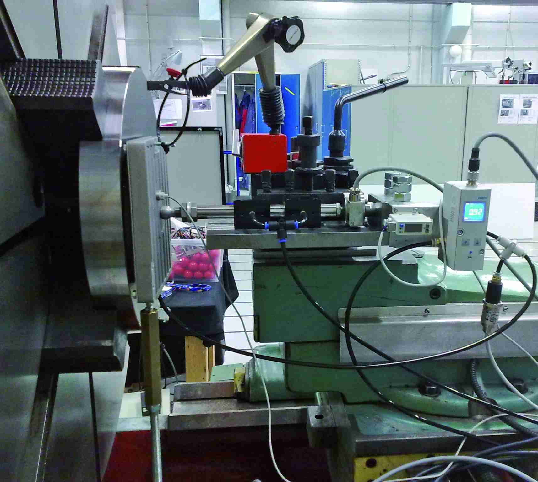
The test bench has been set up on a big-size lathe equipped with a stiff structure and precise guideways and with adjustable speed from 5 rpm to 500 rpm (fig.1).
The loading mechanism is shown in figure 2. The compression is regulated by the manually controlled screw of the sliding saddle of the lathe. A force transducer, installed on the bearing support, measures the load of the support itself. The test support is mounted at the extremity of a shaft with threaded pin and a ball joint. The joint allows arranging the support in parallel with the opposing surface. The alignment is obtained by using strike blocks with 10 mm of thickness between the flat base of the support and the opposing surface. The rod with 20-mm diameter is guided by an aerostatic support that allows an axial frictionless motion. The force transducer mounted in series with the shaft by means of a threaded joint rests against the fixed base.
Layer height and bearing distance from the opposing surface
The layer height and the support alignment for the porous bearings is measured by 3 induced current displacement sensors directly attached to the support, the structure compliance does not influence the load and the interstice height measuring. In air bearings, the air layer is generated between the flexible membrane and the opposing surface. This makes the measuring of the interstice height very difficult. Instead of the interstice height, it is measured the distance between the base plate of the support and the opposing surface.
Data acquisition
The measures have been stored on a PC by using an analogue-digital card and the measuring duration is on average 10 seconds. After each measuring, the datum is saved on a file. The measure analysis with a steady opposing surface is based on the average data of each channel. With the porous support, it was possible to carry out a dynamic test with a larger rotation opposing surface.
The achieved data analyses are based on the synchronized average of load displacement and air consumption.
Supports in test and opposing surfaces
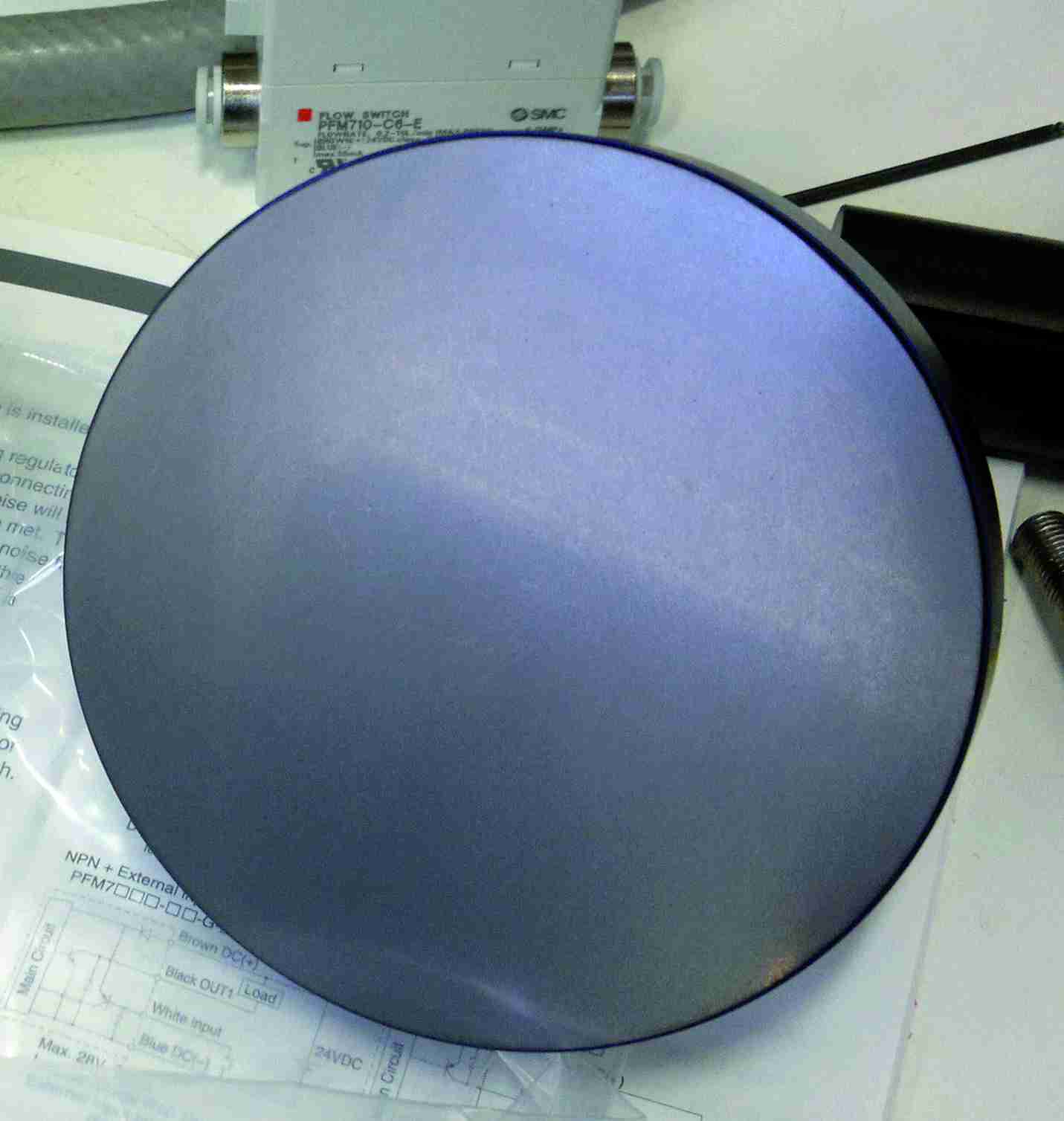
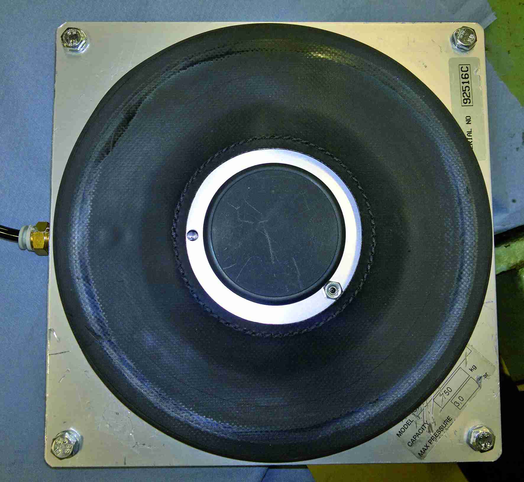
They used two types of air supports in the study (fig. 3): a porous support and an air bearing. The porous support diameter is 100mm. The diameter of the air bearing base is 200 mm. The circular contact area of the rubber membrane varies during the operation, but on the basis of the wear signs that are visible at the test end, the real diameter is around 18 cm. The membrane is attached to a subtle aluminium plate connected with a stamped aluminium frame. During the experiment, the membrane takes a circular shape, having a cross section that is comparable to a tear, with the roundish parts towards the outside and the sharp part oriented towards the pressurized chamber.
Achieved results
Both opposing surfaces have been used, both the stationary (not rotating) and the moving one (rotating). The measured magnitudes are the air flow, load, support and/or feeding pressure.
Test with porous support
The pressure supplied to the pad was 0.52 MPa. While measuring with the still opposing surface, the weight has been increased or diminished in 100 – 200 N scale. After the weight regulation, the support was stabilized for about 60 s before the value registration. With the rotating surface, the maximum load was fixed by the compression of the spring suspensions while the surface was at the highest value.
The support stiffness was measured in relation to the surface of the stationary test disk. The load was increased until when one of the displacement sensors measuring the layer indicated the contact with the surface. Measures were made in both directions, both with increasing and decreasing load values (figure 4).
Tests with air bearings
The loading capacity and the air loss of the air bearing were measured in contrast with the test disk surface. Measures were performed with three different levels of input pressure. The measuring started with a distance of 10mm between the base plate of the support and the opposing surface. The distance was increased until when either the pressure (or the load) dropped or the value of air flow rate exceeded the measuring range (200 L/min). The load and the flow rate were measured in opposition to the rotary surface.
Energy consumptions
To estimate the energy efficiency, the power consumption in the support and in the system are calculated as product of the air flow by pressure.
The variation in the measured power consumption at this stage is shown in figure 5 (series of tests with 0.3 MPa with nominal pressure of the support and non rotating opposing surface).
Analysis
The characteristics of the supports in this study are slightly different one another. Owing to the big differences, a direct comparison of these support types would not be useful. Vice versa the study should be seen as research for an initial sturdy industrial support, solution for two different starting points. The porous material support operates with a very small interstice and its stiffness rapidly grows when the interstice diminishes. These results agree with the common knowledge concerning air supports. The interstice of the air bearing cannot be measured and it is clear whether the membrane is in contact with the opposing surface. Apparently, when the air consumption is minimal (especially with 0.1 – 0.2 MPa support pressure), the wear signs on the membrane, Figure 3, clearly show that there is contact with the surface. Besides, when the opposing surface is manually rotated, a small friction is registered at the detachment. Measures of the friction force (the transversal force applied on the support through contact) can indicate when there is contact and when the operation condition of the bearing is reached. The air bearing clearly lacks stiffness, but big variations of distance between the support and the opposing surface can be easily borne without significant variations in the loading capacity or in the air consumption.
With porous material supports, the consumption power remains low under all circumstances; under 52 W for the stationary opposing surface and 22 W for the rotating surface. For air bearings, the power varies depending on the leakage rate. In the low leakage rate, the power consumption is in the same magnitude order as the porous material support, some dozens watts at 0.3 MPa and much less at 0.1 – 0.2 MPa.
Conclusions
Porous material bearings can be good precision supports provided that both have high stiffness (despite the material porosity) and low air consumption. Nevertheless, the opposing surface must be of good quality (typical finished surface for sliding supports and seals). The air bearing can be subjected to a big axial displacement between the support and the opposing surface without problems, with just a minimum change of loading capacity. This is due to the low stiffness of this type of support. For the air bearing, the operational low leakage range can be especially found at low pressure levels. With support pressure of 0.1 – 0.2 MPa, the leakage is inferior to 2 l/min when the distance between the support and the opposing surface is approximately shorter than 16 mm. This can be very profitable when we tend to good energy efficiency. Apart from that, it is not clear whether the rubber part acts as sealing bearing in this low-leakage modality; future studies will be useful to determine whether non-contact conditions can be achieved without excessive air consumption. If the low leakage indicates contact, then the membrane will determine consumption and friction heat that will be generated when the support will run at the highest sliding speed. With pressure of 0.3 MPa, the low leakage zone is much stricter than 0.1 – 0.2 MPa.
After the low leakage zone, the dispersion rapidly increases depending on the distance.
Both types of tested support can operate with low air consumption and therefore provide valid energy solutions for air supports. Air bearings need anyway future tests to clarify whether the low leakage must be associated to the contact with the membrane, which can require a constant control of use conditions.


