

The integration of a pneumatic valve into a pneumostatic pad allows increasing its stiffness and improving performances. The valve design aims at its integration on the pad itself.
Pneumostatic pads are widely diffused in all those industrial applications requiring very high positioning precisions. Linear guides and micro-positioning systems represent some examples of this particular support typology. Unlike rolling bearings, in pneumatic bearings there are no elements in direct contact between surfaces in relative motion but a thin layer of pressurized air is interposed and allows them to move with very low friction. This possibility makes pneumatic bearings suitable for positioning-precision applications and very high rotation speeds. In pneumatic supports, the bearing action is due to the distribution of pressure generated in the air meatus that separates the mobile element from the stationary part of the guide. In terms of design, the main target is obtaining systems with high loading capacity and stiffness, minimizing air consumptions. Increasing stiffness is advantageous because it allows limiting the variations of meatus height owing to possible variations of applied load and then achieving more precise drive systems. The stiffness of air bearings can be increased with various methods (defined compensation methods) that use different typologies of control systems. It is possible to distinguish active and passive control systems. Active control systems exploit elements (actuators, sensors and controllers) that need additional energy sources with regard to the one used for the bearing operation. On the contrary, passive systems exclusively exploit the bearing supply pressure; the regulation occurs by modifying the passage section of the supply air through variable resistances. Bibliography presents different examples for both compensation typologies.
In [1] is shown a prototype of active pneumostatic pad obtained through the integration of a commercial bearing, a deformable mechanism, a piezoelectric actuator, a position sensor and a PID controller. When sensors detect some variations of the position of the element supported by the bearing, the controller opportunely modifies the stroke of the actuator to restore the initial work condition. The tests carried out have demonstrated that this system, due to infinite static stiffness and a wide passband, assures great reliability in both static and dynamic field.

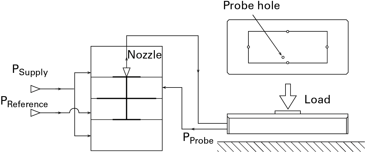
The reliability of piezoelectric actuation systems is also confirmed in [2] where, controlled by a closed-loop control system, they are used to vary the meatus geometry. Even if very efficacious, the diffusion on industrial scale of active compensation techniques is unfortunately inhibited by their complexity and still high costs. Passive compensation methods provide still satisfactory results in static field, with much lower manufacturing costs than the previous typology’s. They consist in the use of deformable elements inside the pad that modify its input or output resistance [3]. The compensation can also be obtained with pneumatic regulation valves (active or passive, depending on the operation principle) integrated in the bearing [4]. In this article, we are presenting a prototype of active pneumostatic pad implemented by integrating a pneumatic regulation valve, purposely designed, with a commercial pad. The tests carried out show how such low-cost solution is interesting for the performance improvement. The prototype of the regulation valve is similar to the one used in a study carried out for the control of the radial position of a pneumostatic bushing [5]. Unlike the previous prototype, the valve has been redesigned choosing suitable geometries and components for significantly reducing footprint sizes (by about 35%) and for making it easily mountable on a large part of pneumostatic pads on trade. Figure 1 shows a section of the valve (Figure 1a) and a scheme that describes its operation principle (Figure 1b). As represented in figure 1a, the valve has four chambers, two external (1), (2) and two central (3), (4). The two outer ones are kept at the supply pressure, one of the two allows supplying the pad through the nozzle (5). The central chambers are supplied respectively at a constant pressure, said reference one, and at a variable pressure taken inside the meatus through a probe hole. Three deformable diaphragms separate the external chambers from the central ones, assuring the sealing and permitting the stroke of the shutter (6).
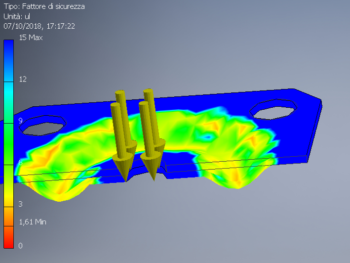
The flow rate of the supply air provided to the pad is adjusted according to the passage distance generated between the shutter and the nozzle. Figure 1b shows the connection scheme of the valve to the pad. Under nominal operation conditions (nominal height of the meatus) the forces stemming from the probe pressure, the reference pressure and the reaction forces on diaphragms, act on the shutter to keep it at a certain distance from the nozzle. If the load applied on the pad decreases, the height of the meatus increases and then the probe pressure diminishes. Consequently, a new balance is re-established on the shutter that approaches the nozzle. This implies a reduction of the supply pressure of the pad and then a partial compensation that allows keeping the height of the meatus under the pad very close to the initial value. The opposite happens if the load rises. Important design parameters are the stiffness of diaphragms (materials, sizes), the sizes of air ducts, of the nozzle diameter and of the supply holes of the pad. The stiffness of diaphragms is very important, for that reason the shutter’s mobility has been investigated by using diaphragms of different material (steel, nitrile rubber) and of different thickness. Figure 2 shows an example of the analysis of the deformation status of a diaphragm made by using finite elements. The sizes of the holes of pad and nozzle were chosen so that the operation of the active system under nominal conditions is comparable with the one of the only commercial pad not controlled.
Experimental tests
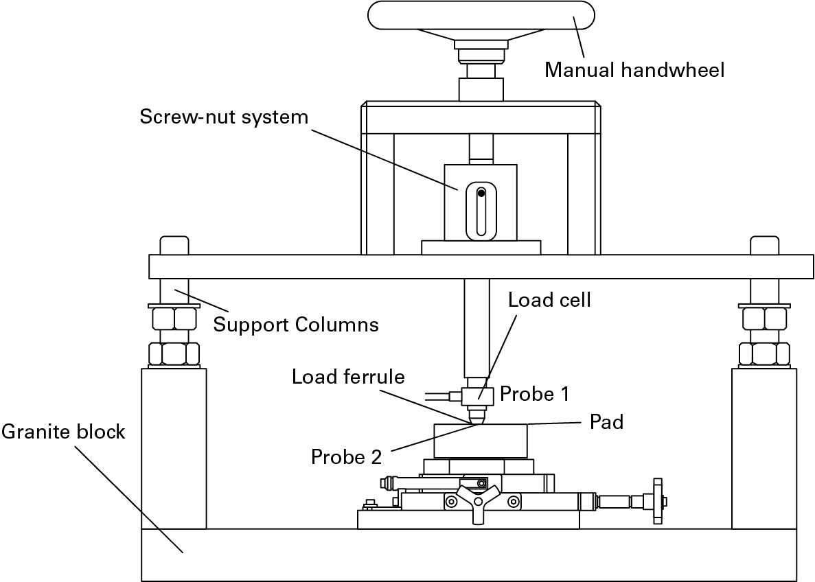
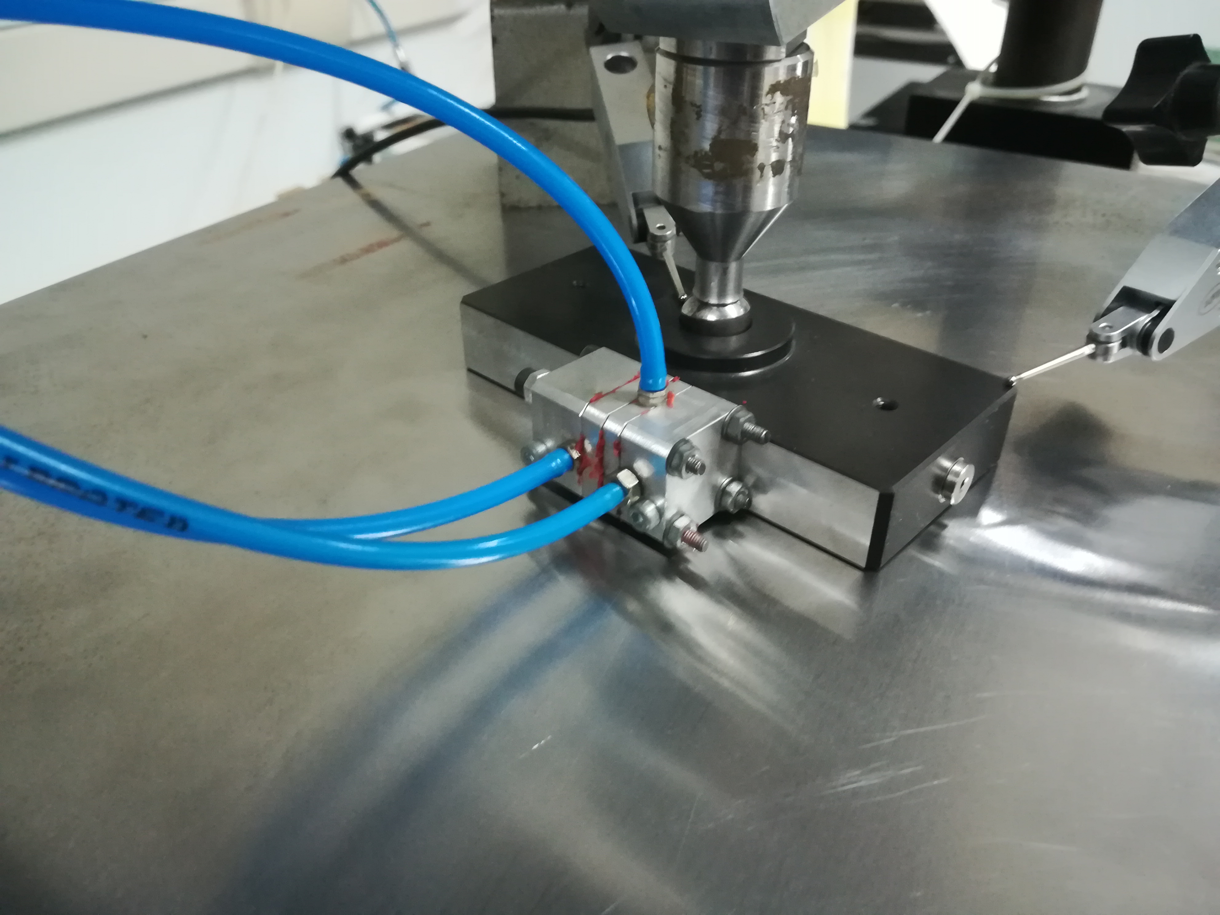
The static characterization of a pneumostatic pad consists in drawing experimentally or numerically the characteristics of lift, air consumption and stiffness when the meatus height varies. Experimental tests were carried out with an appropriate test bench. Figure 3 shows the scheme of the test bench, in figure 4 the pad mounted on the bench is visible. During the test, the pad rests on the surface of the test bench and is loaded by means of a spherical ferrule moved by a screw-nut screw system. The values of the meatus height are acquired by using two electronic probes laying on the upper surface of the pad (Figure 4). To evaluate the bearing displacement uniformity, the first probe is positioned close to the loading ferrule while the second close to edges. The load supported by the bearing is measured by a load cell placed immediately upstream the ferrule. Acting on the handwheel, you set different meatus heights and you measure the values of force, airflow and probe pressure.
The bearing stiffness is afterwards deduced from the ratio between the lift variation and the meatus height variation.
Results
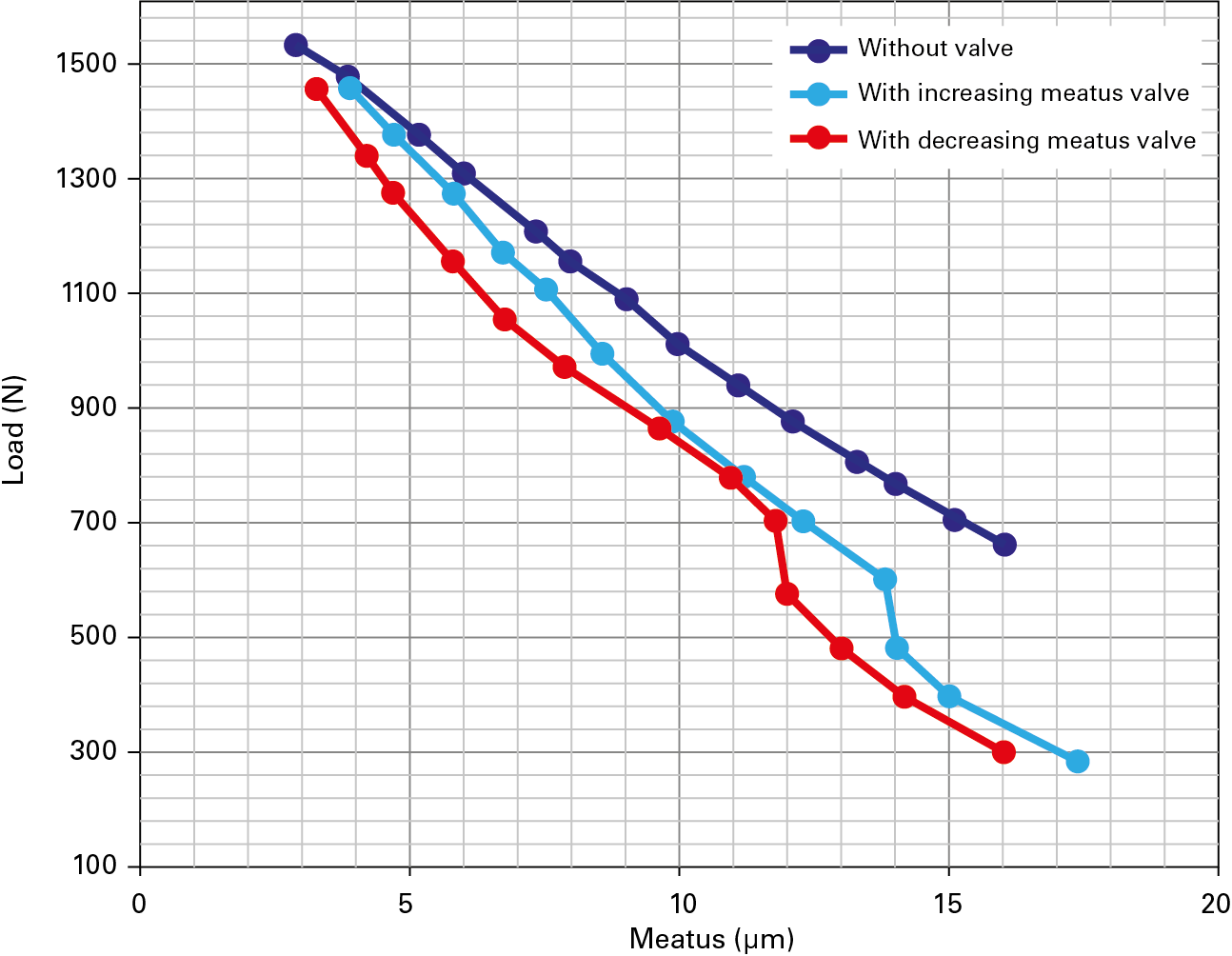
The experimental results of lift and air consumption of the active pad were obtained according to the meatus height. To assess the efficacy of the control system, results are compared with the ones of the pad on trade without valve. Measurements were carried out when the meatus height both increased and decreased, to observe the hysteresis phenomenon connected with the typology of diaphragms used. Measurements were repeated with some reference pressures. Figures 5 shows for instance the experimental trends obtained in a specific measuring condition. It is evident how the regulation action in a certain meatus range implies a notable rise of slope in lift curves. The stiffness of the active pad is more than twice higher than the only commercial pad’s. The slope variation occurs in a more or less restricted meatus range, according to the rigidity of the valve’s diaphragms. It was also assessed that acting on the reference pressure it is possible to modify the height of the nominal meatus according to which to operate the regulation.
Conclusions
In this article, we have described some compensation methods to increase the stiffness of pneumostatic pads. We have in particular presented a solution that integrates a valve purposely designed in a commercial pad. The system stiffness has been relevantly increased without modifying the air consumption significantly. Other significant advantages obtained consist in the possibility of adapting the same valve to different pads on trade and in the possibility of selecting the regulation field easily modifying the reference pressure. Although they show some design aspects that can be improved, the results obtained after the first experimental tests prove the efficacy of the proposed method. Studies are currently in progress both to improve the static performances of the system and to investigate its dynamic behavior. www.polito.it


