
– Vincenzo Cuffaro, Francesca Curà, Andrea Mura
Politecnico di Torino, Department of Mechanical and Aerospace Engineering, C.so Duca degli Abruzzi 24 – 10129 Torino Italy.
Spline couplings are mechanical components used to connect and transmit torque between two rotating shafts. A spline coupling consists of two parts: a shaft with external teeth and an hub with internal teeth; the load is transferred from the shaft to the hub (or vice-versa) by means of a number of engaging teeth.
Since these components are usually over dimensioned concerning both static and fatigue behavior (or at least doesn’t presents particular problems), their weak point is the wear phenomena that may affect the teeth surfaces [1], [2].
In particular wear phenomena such as fretting wear appear on teeth surface when a relative motion between engaging teeth is generated. The relative displacement between teeth may be generated by vibrations, cyclical tooth deflection or misalignment between hub and shaft: this point has been investigated in this work [3].
Misalignment between hub and shaft may be due to manufacturing and assembly tolerances. An interesting and significant case of angular misalignment is the angular misalignment that present in particular in aerospace applications [4], [5].
Currently design criteria that can be applied to components to predict fretting damage are not available. Nevertheless design criteria are needed in order to check components about this phenomenon, avoiding the formation of this type of damage or at least to keep it under control. For these reasons, in recent years an increasing interest is growing for the study of the fretting, both with regard the scientific community, both in the industrial world. In particular, regarding spline couplings, a research group of the Politecnico di Torino started a research activity about the wear phenomena caused by the misalignment between hub and shaft.
Straight and crowned teeth spline couplings
Spline couplings are classified according to the tooth profile along the radial direction (involute profile ,straight parallel profile,…), the engaging conditions (side fit, diameter fit) and the tooth profile along the axial direction (straight teeth and crowned teeth) [6].
This last classification is very interesting for what concerns the component behavior and the wear damage when an angular misalignment is present between hub and shaft.
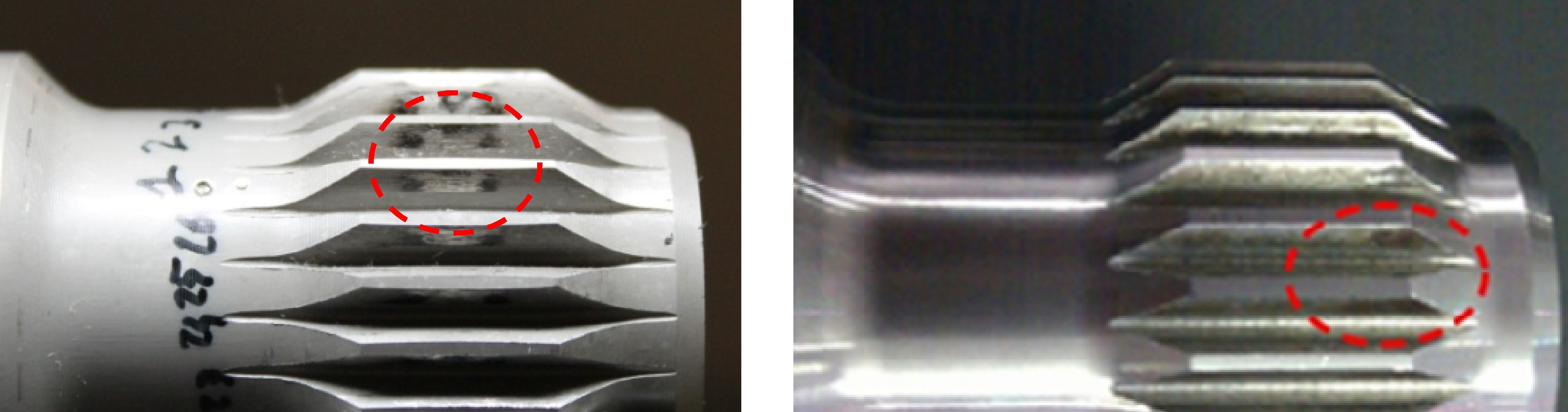
Figure 1 shows the difference between two involute spline couplings with the same geometrical parameters (modulus, teeth number, pressure angle, etc…) but the one on the left has straight teeth and the other on the right presents a crowing radius.

When these components are working in misaligned conditions, the contact regime between engaging teeth totally change if the teeth present on not a crowing and this brings to different wear pattern on the teeth surface [7].
If the tooth is considered as a rigid body, in the case of straight teeth, only one point at one edge of the tooth will be in contact (in the real case, because of the tooth deformability, the contact region is a kind of rectangular area); this brings to the formation of wear phenomena located at the extremities of the tooth width (Figure 2 left).
On the other hand if a crowned tooth is considered, the contact area comes from an Hertian contact and the wear phenomena will be located near the center of the tooth width (Figure 2 right).
Surface wear damage
The Ruiz parameter R1 [8], initially formulated for fretting fatigue in dovetail applications, is considered here for identifying the attitude of spline couplings teeth surface to be subjected to fretting wear damage, particularly for its emphasis on the slip amplitude as a key variable on fretting wear:
(1) R1 = T . d
where is the surface shear stress (that is the multiplication between the coefficient of friction m and the teeth contact pressure P), is the relative slip amplitude between the two surfaces.
Pressure distribution depends on both contact geometry and load conditions, while relative displacement is due to the component misalignment and may be calculated by means of kinematical considerations.
The Ruiz parameter is calculated here along the spline axial direction and along the transverse tooth involute in order to obtain a kind of Ruiz map of the contact surface.
Experimental tests
Preliminary wear test presented in this work have been performed by means of a dedicated spline coupling test rig (Figure 3) [8]. Thanks to this test rig it is possible to make tests with a spline coupling specimen working in misaligned conditions causing wear phenomena on the engaging teeth. The test rig operates on a torque-regenerative principle in which torque is circulated in a loop, allowing low energy consumption. Components may be loaded by a constant torque up to 5000Nm; the maximum rotating velocity is 2000 rpm [8].

As an example, Figure 4 represents a tooth of steel crowned spline couplings test articles (26 teeth, 1.27mm modulus, 30° pressure angle) after wear tests performed respectively with the following working conditions: A) 700Nm torque, nil misalignment angle, lubrication active (Figure 4A), B) 700Nm torque, 5’ misalignment angle, lubrication active (Figure 4B); C) 700Nm torque, 10’ misalignment angle, lubrication active (Figure 4C); D) 700Nm torque, 10’ misalignment angle, lubrication not active (Figure 4D).
It is possible to observe that the tooth represented in Figure 4A doesn’t show any wear damage; this is because the first test has been performed without misalignment and this means that no relative motion between engaging teeth was present and so any wear action on teeth surface were present.
Figures 4B, 4C and 4D represent teeth after tests on which an angular misalignment has been imposed; this brings to a relative motion between engaging teeth and so wear phenomena appear on the contact surface, visible approximately at the middle point of the teeth width. It is possible to observe that the wear area has approximately an elliptic shape, this is due to crowned tooth width that allows an hertian contact pressure, as described before.
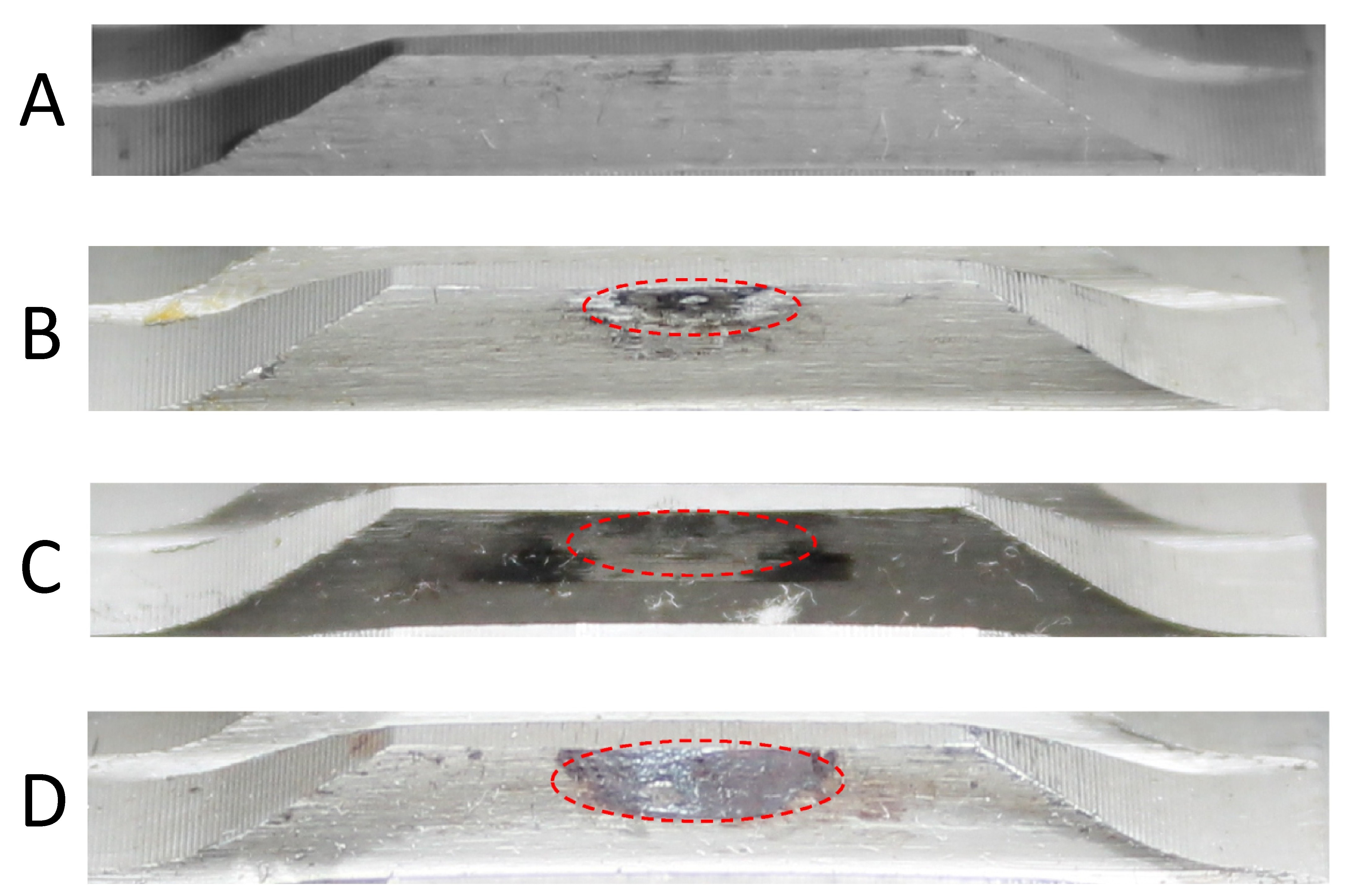
Figure 4: Spline coupling test article after tests A, B, C and D.
By comparing Figure 4B and Figure 4C it is possible to point out that wear phenomena are more intense by increasing the misalignment angle and, considering Figure 4C and Figure 4D, that also the lubrication has a very important role: teeth after test performed without lubrication present a more deep wear with respect to those run with the same loading and misalignment conditions, but with active lubrication.
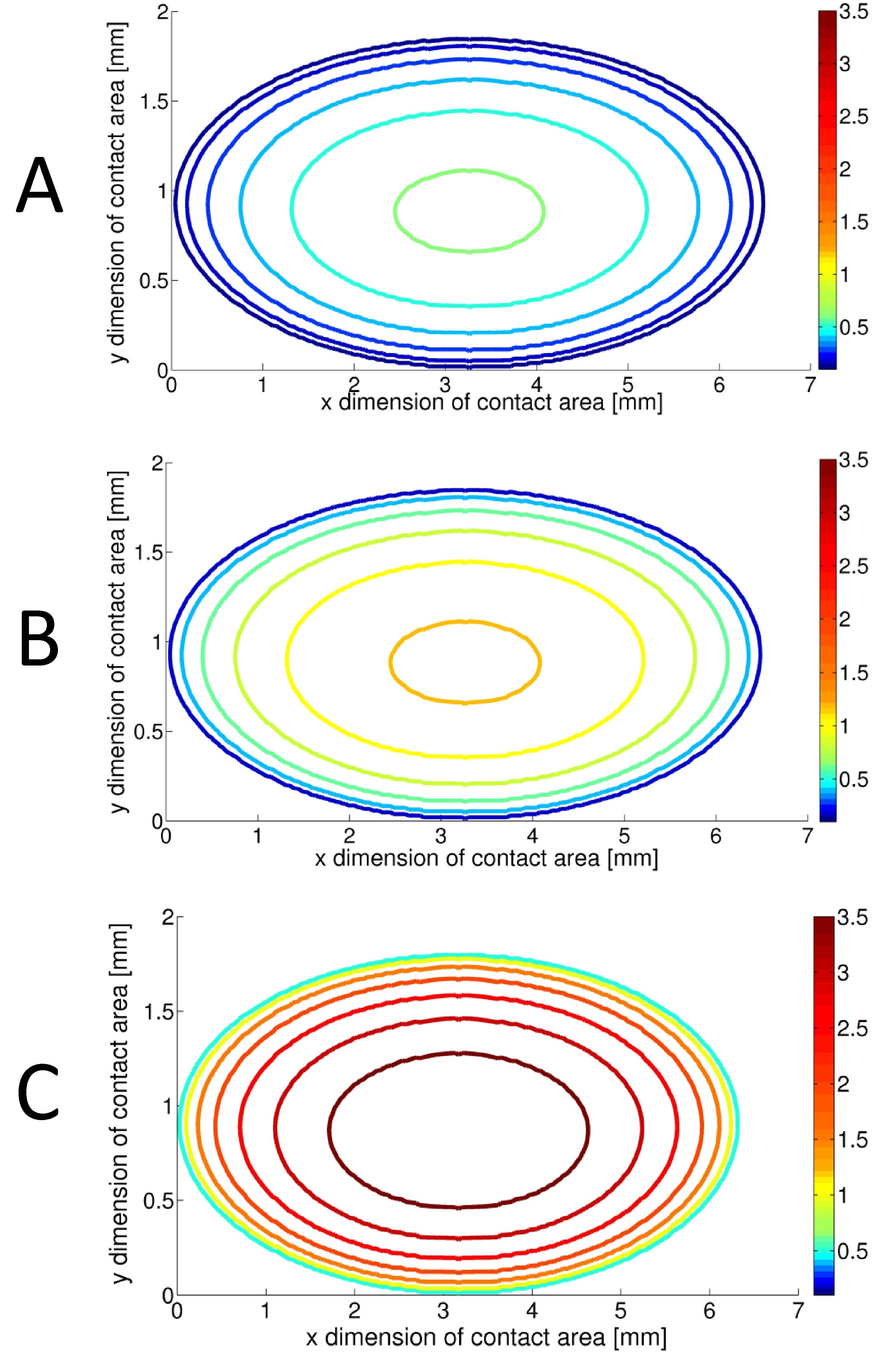
By analyzing the Ruiz map obtained considering tests B, C, and D (test A has not been considered because the Ruiz parameter of this test is equal to zero because there is any relative motion between teeth) and represented respectively in Figure 5, it is possible to obtain the same conclusions seen for the experimental tests. In particular, it is possible to observe that the Ruiz parameter is higher where the wear damage is more important, that is at the center of the contact region.
Conclusions
In this work an experimental and theoretical study about fretting wear damage on crowned splined coupling has been conducted.
Experimental tests have been performed, by means of a dedicated test rig, on specimens working in misaligned conditions and the effect of both angular misalignment value and lubrication condition has been analyzed.
The Ruiz parameter has been adopted in order to set up a theoretical model capable to simulate the attitude to allow wear damage on crowned splined couplings.
The theoretical model considers the real working conditions in terms of angular misalignment, transmitted torque, lubrication and surface conditions.
The comparison between experimental tests and theoretical Ruiz maps shows that where the wear damage is more important, the corresponding Ruiz parameter value is higher.
From these results it is possible to conclude that the theoretical model based on the Ruiz parameter may be used to predict the attitude of a crowned spline coupling to be affected to fretting wear damage.
A future work it will be possible to apply the fretting wear evaluation procedure presented in this work in to experimentally identify an “allowable Ruiz parameter” for fretting wear: under that limit the damage phenomena doesn’t occur in the components.
References
[1] G. Curti, F. Curà, V. Cuffaro, A. Mura, Calcolo degli accoppiamenti scanalati: i metodi tradizionali, Organi di trasmissione Maggio 2010 pp. 64-73 ISSN: 0030-4905.
[2] F. Curà, A. Mura, M. Gravina, Load distribution in spline coupling teeth with parallel offset misalignment, ProcIMechE Part C: J Mechanical Engineering Science Vol. 227 Issue 10 October 2013 pp. 2193 – 2203 DOI:10.1177/0954406212471916.
[3] V. Cuffaro, F. Curà, A. Mura, Analysis of the pressure distribution in spline couplings, Proc IMechE Part C: J Mechanical Engineering Science (2012) 226(12) 2852–2859, DOI: 10.1177/0954406212440670
[4] F. Curà, A. Mura, Experimental and theoretical investigation about reaction moments in misaligned splined couplings, Mechanical Systems and Signal Processing 45 (2014), pp. 504–512, DOI: http://dx.doi.org/10.1016/j.ymssp.2013.12.005.
[5] F. Curà, A. Mura, Experimental procedure for the evaluation of tooth stiffness in spline coupling including angular misalignment, Mechanical Systems and Signal Processing 40 (2013) 545–555, DOI: 10.1016/j.ymssp.2013.06.033.
[6] V. Cuffaro, F. Curà, A. Mura, Accoppiamenti scanalati: classificazione e danneggiamento, Organi di trasmissione – Aprile 2013 pp. 22-25.
[7] V. Cuffaro, F. Curà, A. Mura, Experimental investigation about surface damage in straight and crowned misaligned splined couplings, Key Engineering Materials Vols. 577-578 (2014) pp 353-356, doi:10.4028/www.scientific.net/KEM.577-578.353.
[8] V. Cuffaro, F. Curà, A. Mura, Test Rig for Spline Couplings Working in Misaligned Conditions, Journal of Tribology 136(1), January 2014, doi:10.1115/1.4025656.


Dear Mrs. Anna Bonanomi,
Thanks for the interesting research.
I have question regarding the test rig. Who is the manufacturer of the test rig which you used for your experimental tests? Do you have a list for test rigs manufacturers? or do you know some testing institutes who have such testing machines in their laboratories?
Thanks in advance
Kienan Al Khatteb
Dear ing. Kienan Al Khatteb,
we are glad you appreciated the content of our digital magazine.
For any request about the test rig, you could directly contact one of the Authors to the following address:
andrea.mura@polito.it
Kind regards
Anna Bonanomi Editor