Maurizio Poggiali –
The fibre transport with air represents an important element in several textile industries. At present there are no alternative methods to carry fibres having at least comparable efficiency. In the article are illustrated the problems generally present on plants and deriving from a deficiency in the design and study phase. Besides, it is indicated a method to obtain an effective design, processed and tested on a pilot plant.

In the ambit of the project “EFFECT: Energy Efficient Fibre Transport”, MANUNET ERA-NET Project, Kentec, Konus Konex and Next Technology Tecnotessile took care of carrying out some analyses and some simulations, both numerical and practical, in order to obtain a significant reduction of the energy consumption in the transport of textile fibres by means of channelled air flows. In the production of non-woven fabric and also in spinnings, fibres are transported with the aid of an air flow inside transfer tubes from a process machine to the other. To this end, exhausters are traditionally oversized in order to assure an adequate supply of fibres, thus avoiding the onset of defects in the processing. An estimate reveals that companies spend about 13,100 € per year (hypothesizing a cost of the electrical energy of 0.10 € per kWh) to power a fan of medium size, mounted on the production line. A simple calculation shows that the energy costs of a single production line (having 6 fans for the fibre transport) along the life cycle of machines amount to about 1.5 million €. Kentec and Next Technology Tecnotessile have availed themselves of the most modern technologies for the process simulation and of laboratory measuring instruments for the detection of all physical parameters at stake.
The transport of textile fibres by air
In the production process of non-woven fabrics the used fibres are processed and transported on long distances in transport tubes, to be distributed to machinery like for instance the packing machine, and the mixer. An air flow is used as transport means for the said fibres. Inside the tube, during the feeding of the fibrous mass, we have a mixture composed by fibres for one third of the volume, and by two thirds of air. The air in the tubes normally travels at an average speed of 20 m/s. For the transport of this mixture along the whole course of the productive line, they use some fans that have an average consumption of energy varying from 11kWh to 15 kWh.
At the current state the majority of the operating plants has not been designed taking into account the pressure drops induced by constrictions, bends, bifurcations and, first of all, by the diameter and the length of the tubes themselves, but the single criterion used for the implementation was to transport the fibres to the machines, avoiding the obstacles existing in the used environments. Actually, the courses and sometimes also the diameters have been adapted to the available layout. In this way, however, it has never been considered what type of efficiency might have the fibre transport on the production line. The solution was, as already said, to install an oversized fan. This simple solution sometimes leads to an obstruction of tubes, deriving from fibre accumulations, especially in low radius bends or in “Y”-shaped couplings, which cannot be displaced despite the introduction a very strong air flow. This results in a rise both of the energy consumption and of the waste fibres. Due to that, today the production process of non-woven fabrics is not optimized from the point of view of energy consumptions.
The reduction of the energy consumption inside the productive cycle in the textile sector was then the final target that the EFFECT project decided to reach, through the implementation of a new system of calculation and modelling of plants, processed in order to reduce flow resistances and, consequently, the energy waste. This optimization is made possible by a correct sizing of fans, tubes and by an efficient arrangement of all the parts that induce flow resistances.
To develop the said calculation and control system, the plant by KONUS has been taken as practical example. That plant was conceived according to the standard concept previously expressed of “bringing the fibre where it is needed” mainly taking care of avoiding the physical obstacles that stand on the path. We can observe an exhaustive example of the modus operandi in figure 1.
These curves positioned very close to the fan inlet clearly have a totally negative effect on the suction efficiency. The pressure drop induced by this tube length corresponds to about 32.4 metres of straight piping. The presence of numerous similar cases on the plant makes us understand what are the improvement margins and, especially, how much energy it is possible to save if we take care of designing and calculating the layout correctly.
Project of a pilot plant
Not having the possibility of intervening directly on the installation by Konus, they opted for carrying out some studies on a “pilot plant” by the laboratories of Next Technology Tecnotessile of Prato (Italy).
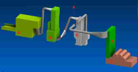
The designed line is composed as follows (fig. 2):
- A) feeder with spiked lattice
- B) loading silo
- C) launch fan
- D) card loader
- E) fixed flat card
- F) tube length of transparent acrylic material
For the correct sizing of the air ducts, for the definition of geometries and the space definition, it has been used a software for the computational fluid-dynamic simulation. The behaviour of the air inside a duct with known geometry is relatively simple to be modelled and to be foreseen. In our case, on the contrary, together with air they had to transport a fully inhomogeneous fibrous mass, whose behaviour has not been studied in-depth, yet.
Therefore, the fluid-dynamic simulation of the motion of the flakes inside the tubes was set through a series of surveys that were useful for determining the fluid-dynamic characteristics of the flakes themselves.

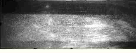
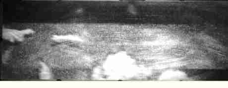
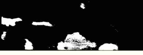
They proceeded then with measures aimed at experimentally determining the single variables at stake. In order to characterize the flakes, a sample was taken from the feeding line. Some flakes were weighted and they made some shots of their fall in still air, in order to measure their falling speed. The analysis of those shootings has allowed determining the viscous falling speed of fibres that, coupled with their weight, has permitted to establish the aerodynamic characteristics of fibres (particles) used in the numerical simulation. The average falling speed resulted to be included between 0.8 and 2 m/s, the characteristics of density and diameter of the particles in the simulation were set in such a way as to replicate that value of viscous falling speed. The dynamic characteristics of the fibre flakes depend also on the air mass incorporated in the flake. That mass does not contribute in the weight force because it is balanced by the floating force and therefore it does not influence the falling speed but it instead participates in the inertial effects. Considering that the air weighs about 1.2 grams per litre and that a flake weighing 1 gram takes up a volume of approximately 0.3 – 0.6 litres, we easily deduce that the mass to be considered for inertial purposes is about 50% higher than the mass measured by the balance. In order to model accurately that characteristic, they have acted by decreasing to 6.5 m/s2 the gravity acceleration value and restoring, in the model, the suitable density values of the flake material for simulating the right falling speed. The particles used in the simulation show a constant density but a range of diameters that varies, with Gaussian law, by a factor 10. The fluid-dynamic simulation software has then calculated the particle motion considering also the turbulence effect, simulated through the addition of a random speed component proportional to the turbulent kinetic energy. The plant piping was designed with the drawn data. Once implemented, they have made some modifications on machine to assess how flakes really behave during the processing. They prepared a card of the experimental room, through the installation of transparent windows. The windows were realized on the feeding pipe in the zone immediately above the silos. Using a fast camera, they made some shots lighting up the scene by means of two spotlights placed above and under the horizontal centreline of the window to reduce reflections as much as possible. They made at least 6 shots for each position, by varying their frame-rate, at least 3 of them at 250 frame/s for each processing. The shooting processing which was enabled by a series of algorithms in Matlab language, occurs in two steps: in the first step it is calculated the mean image of each shot (fig. 3) “the background “, this is subtracted to each frame (fig. 4).

In the second step it is used a particular function able to identify the homogeneous areas of an image and to provide some characteristics of those areas, such as: surface, position of the centre of gravity, eccentricity etc. Calculating the differences of two successive frames it is then possible to follow a determinate area, looking for it among those with comparable area that have not undergone a displacement exceeding a determinate preset limit. When the algorithm identifies the same area in two successive frames, it updates the displacement matrix in all the points that belong to the considered area summing the detected displacement to it; besides, it updates a counter matrix that keeps track of how many samples were summed in each pixel. What is obtained at the end of this process is then a matrix that contains the average displacement vectors. Besides, it was highlighted that the measured displacements are those of fibre flakes that do not directly coincide with the speed vectors of the air flow, even if the two fields are strictly related.
An efficient air transport system
Once validated the mathematical model and made some detail modifications to the plant, they positioned some sensors, which operate inside a “closed loop” system and which supply in real time:
– number of revolutions of the fibre launch fan;
– current absorbed by the fan;
– air pressure at the fan output;
– air pressure before the transparent tube length;
– air speed;
– air flow rate.
Under the transparent tube they have installed a camera connected with a computer where were stored also the data of the sensors acquired through purposely developed software. Kentec has provided for processing specific software that analyses the dispersion of the flakes in the air, correlating it with the pressure, speed and flow rate data read inside the tubes. It was initially possible to assess that fibres are not absolutely altered or damaged by the use of air flows for their transport to utilities. The relative facility of generating such flows and the perfect compatibility with the fibrous matter certainly make air an excellent means for the fibre transport. Besides, the air current tends to further open fibres and to separate eventual fibrous clusters formed in the preparation phase. If the development of tubes is not extremely short, the air tends also to distribute the fibres homogeneously inside the available volume, in this way the fibre accumulation in loading silos occurs uniformly along the whole working height, thus favouring the implementation of a qualitatively higher product. The software can then calculate the homogeneousness of the fibres-air mix and it can know the surrounding conditions that have generated such distribution of flakes. This control system proved therefore to be able to determine the correct fan speed automatically, intervening on the inverter that controls it, optimizing its energy consumption, irrespective of the tube layout and of the variation of the quantity of incoming fibres. Using various fibres, from cotton to wood and to synthetic fibres, alone or mixed together, they made tests at various rotation rates of the fan motor, to determine the different behaviour of the fibres in the air flow, the influence exerted by the various materials on the efficiency of the transport with air and also the ideal speeds of the air-fibre fluid. The acquired data were afterwards analysed and assessed in order to identify what are the ideal parameters that grant, besides the good transport quality, the highest energy efficiency. The information collected in the whole experimentation campaign were used to form an important data library supporting the effectiveness of the developed system.

An unexpected result, but very important of the research, consisted in assessing that the fibre density is not the prevailing characteristic concerning the efficiency of the transport mechanism. It was generally wrongly assumed that: the minor is the density of the fibrous mass the more efficiently it can be transported. Analyzing the collected data it was demonstrated that the most complex mechanisms are involved in the fibre transport in air and primary roles are played by factors like: fibre/air friction coefficient, the variations of the surface tension and the mechanical bind among fibres themselves. It was in fact verified that if the “mechanical structure” and the network strength was less strong, it was easier for the suction fan to separate (or to suck) the flakes into single fibres, making the transport easier and more efficient.
Finally, they drew up some guidelines on how the process parameters of the preparation and distribution line influence the quality of the transport of fibres themselves. These guidelines are useful to obtain the highest efficiency of the plant, without having to execute a high volume of tests and setups. It is clear that such “rules” are of general character and that the effective “fine-tuning” will be necessarily carried out on the plant.
Conclusions
The research carried out has highlighted how to provide the knowledge and the technical-scientific means, needed for a correct design and management of plants, leads to optimize the energy resources for a rational energy use. Obviously, there will be the double advantage of a much more efficient fibre transport and an energy saving that will significantly influence production costs.


